randys blog


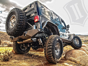
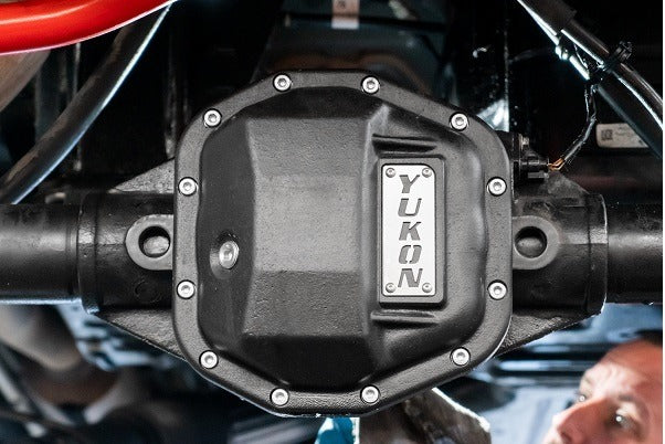
Yukon Hardcore Diff Covers: A Fortress of Tough Nodular Iron
Upgrade Your Diff Cover and Avoid Costly Repairs Yukon Hardcore Diff Covers are designed to protect lockers, gears, and axles from the abuse that makes wheeling an adventure. Yukon covers are constructed from thick-walled, high-strength ductile nodular iron to endure the most severe impacts Mother Nature can dish out. They also increase the structural rigidity of the differential, reducing deflection under high-torque, situations that can put severe loads on internal parts. It’s no secret that the underside of your rig can take a beating. Whether you’re deep into a high-angle, high-anxiety rock crawl, pulling rope and winching, or running hard on the track, aftermarket bumpers, skid plates, and rocker guards all play a critical role in keeping vital underbelly components safe. But what about your diff? It’s the lowest hanging fruit and very susceptible to damage. Crack or break a diff cover and you’re done for the day. Stock differential covers can be overwhelmed when the going gets tough. Stamped-steel construction makes them prone to failure. Dent damage can cause interference with ring & pinion gears and spider gears, which will bring your day to a grinding halt. Another failure is cracking. Cracks let gear oil out and allow water, mud, and debris in. Both scenarios will end your fun and lead to large, jaw-dropping repair bills. These misadventures make for some harrowing campfire stories, but it’s always better to talk about the victories of the day. Don’t let this happen to you. Heat dissipation is also a function of a cover’s structural design. To this end, Yukon engineers have contoured the inner surfaces of the cover to circulate oil more rapidly throughout the housing, allowing for faster cooling. This reduces friction, heat, and wear, a classic trifecta of durability. Each Yukon Hardcore Diff Cover includes alloy steel fasteners that reliably seal the housing for leak-free performance. High-quality magnetic drain plugs are employed for quick-and-easy maintenance and some units feature twin fill plugs so you can max out the housing’s oil capacity. Thick-Walled Nodular Iron Cover Takes a Beating Keeps on Wheeling Streamlined Interior Contours Direct Oil Flow to The Pinion Includes High-Strength Alloy Steel Fasteners Heavy-Duty Protection for Added Peace-Of-Mind Style has its place, and these covers look great. They feature a durable black powder coat finish that is contrasted by a stainless-steel “Yukon” accent plate and the cover bolts. Yukon Hardcore Diff Covers are available for many of the most popular differentials. Check out the comprehensive list of applications in the accompanying chart or click through via the ‘Shop All Yukon Hardcore Differential Covers’ button and up the safety-factor of your ride today. Call Now 866-631-0196 Shop All Hardcore Diff Covers Part Number Differential Application YHCC-D30 Dana 30, 10 Bolt YHCC-D30JL Jeep JL Dana 30, 12 Bolt YHCC-D35JL Jeep JL Dana 35, 12 Bolt YHCC-D44 Dana 44 YHCC-D44JL-Front Jeep JL 44 Front, (M220) YHCC-D44JL-Rear Jeep JL 44 Rear, (M210) YHCC-D60 Dana 50, 60, & 70 YHCC-F8.8 Ford 8.8” YHCC-GM14T-M GM 14 bolt Truck, W/ M8 Bolts YHCC-GM14T-S GM 14 bolt Truck, W/ 3/8” Bolts YHCC-GM8.5-M GM 8.5” Metric YHCC-GM8.5-S 1313GM 8.5” Standard YHCC-M35 Model 35 Rear
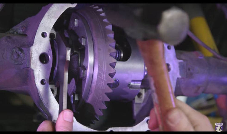
How to set Ring and Pinion Backlash
Once you have installed and set the proper pinion gear depth with either a pinion depth gauge or by the pattern revealed when using a gear marking compound, it’s time to address backlash. Ring and pinion backlash refers to the amount of play between the gears. An abundance of play can become a factor on vehicles that are heavy or rigs that tow or haul hefty loads. Loose tolerances between the gears can cause binding under acceleration and deceleration and lead to noise, overheating, and ultimately gear and/or bearing failure. Shim For The Win It’s always a good practice to start the process with your factory carrier shims. Make sure they’re clean and measure them in three places to ensure a proper fitment. Add some oil to the outside of the shims to allow for easier installation. Start with the right-hand side to prevent tooth binding with the pinion and drive each shim completely into place. Then install the left-hand shims and your carrier should be in place. Dialing It In Once fully seated, install and tighten down the carrier pads. Always install and tighten the right side first. With the carrier assembly installed, attach your dial indicator with the plunger at a 90-degree angle from the face of the ring gear teeth. Gently rock the carrier back and forth to measure your backlash. You’ll want to do this in three separate locations on the ring gear to check for runout. If the backlash is too tight, move the carrier away from the pinion by adjusting the carrier shim. If the backlash is too wide, adjust the carrier toward the pinion. When adjusting the backlash, a rule of thumb is 10 thousandths of carrier shim adjustment will result in around 7 thou of backlash adjustment. Rock the carrier back and forth until little to no free play is evident. To see how setting backlash works check out the accompanying video.
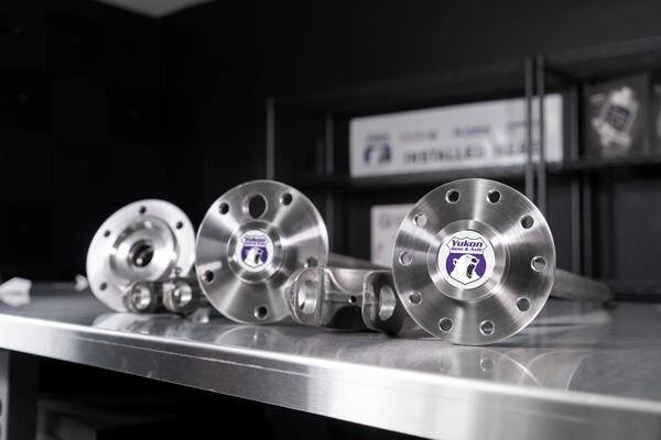
How to Identify Your Differential and Axle Type
How to Identify Your Differential and Axle Type Using year, make and model, and vehicle info is the first/best way to identify your differential. But there are cases where these facts come up short. Your vehicle’s options like tow packages, off-road packages, or whether it sports an automatic or manual transmission can make identification more difficult. Further, if your rig has been modified its drivetrain changes will throw a wrench in the works. Luckily, there are visual cues that can help identify your particular diff or axle. Cover Bolt Count Since most differentials have a unique cover bolt pattern i.e. 10-bolt, 12-bolt, or 14-bolt, counting them up will narrow the field and help you with identification. While focusing on the pumpkin check out what type of housing you have… an integrated housing or a drop-out style. An integrated housing can be spotted by its inspection cover. A drop-out housing has no inspection cover because the entire differential assembly is removed from the front half of the housing. Axle Flotation Another important data point is axle type. There are two types of axles, semi float or full float. Semi-float axles have larger flange diameters than floating axles and the wheel bolts to the flange. A full-float axle flange bolts to the wheel hub and can be removed without taking the wheel off or jacking the vehicle up. Another variable to consider concerns how the axle is secured within the differential... via a c-clip or by bolting the unit in place. Get Your Spline In Line While identifying your axle shafts, it’s important to take note of your spline count. Look at the raised teeth and count these out. This can be tedious. We suggest marking a spline with a Sharpie and starting your count there. You may want to do a recount or two to confirm you’re tally is accurate… we told you it may be tedious. Spec Out Your Hub Another helpful hint in identifying your axle is figuring out how many hub bolts you have, your hub pattern, and your hub diameter. Determining the number of bolts is relatively easy, determining the bolt pattern can be a little more complicated. The best way to do that is by measuring from one stud to the center of the axle flange itself and doubling that number. If you see yourself doing this a lot, there are bolt circle templates that will expedite the procedure. Knowing your hub diameter will help in identifying different years, makes, and models. Pinion Size & Ring Gear Diameter Once your differential is disassembled and its parts removed, it’s time to measure your ring gear to determine its diameter. Simply measure from the widest point of the gear, tooth tip to tooth tip Pinion nut size is another parameter that can be used to identify the diff. This is relatively ease just test fit sockets until you find the one that fits… bingo. For more differential spotting tips check out the accompanying video.
YUKON TAPA DEL DIFERENCIAL HIERRO REFORZADA
Modifique la tapa de diferencial y evite reparaciones costosas. Las tapas reforzadas para el diferencial de la marca Yukon están diseñadas para proteger los bloqueadores, los engranajes y los ejes del abuso generado durante los viajes off road. Las tapas de Yukon están fabricadas con hierro nodular de alta resistencia y paredes gruesas para soportar los impactos más severos que la Madre Naturaleza nos puede brindar. También aumentan la rigidez estructural del diferencial, reduciendo la deflexión en situaciones de alto torque, que pueden imponer sobrecargas en las partes internas. No es ningún secreto que la parte inferior de su 4x4 puede recibir mucho abuso. Ya sea que se encuentre manejando por ángulos difíciles, trepando por las rocas, utilizando el winche, o compitiendo, los parachoques, placas protectoras aftermarket, todas estas en conjunto desempeñan un papel fundamental para mantener seguros los componentes vitales. Pero, ¿qué pasa con tu diferencial? Es el componente más susceptible a sufrir daños. Veamos de esta manera si le causas alguna grieta o quiebras la tapa del diferencial, puedes decirle adiós a tu día de diversión. Las tapas originales del diferencial no aguantan mucho este tipo de abuso. La construcción a base de acero las hace propensas a fallar. Los daños causados pueden causar interferencia con las relaciones piñon corona y los satélites, lo que hará que su día termine muy mal. Otro importante es el agrietamiento. Las grietas dejarán salir el aceite de los engranajes y permitirán la entrada de agua, barro y otro tipo de suciedad no querrás que suceda eso. Ambos escenarios terminarán con su diversión y generarán facturas de reparación muy costosas que dejarán con la boca abierta. Estas aventuras se convierten en historias de horror para ser contadas alrededor de las fogatas, pero siempre es mejor hablar de las victorias del día. No dejes que esto te pase a ti. Una de las principales características del diseño de esta tapa es la facilidad que tiene para la disipación de calor. Con este fin, el diseño de la tapa de Yukon hace que el aceite circule más rápidamente por toda la carcasa, lo que permite un enfriamiento más rápido. Esto reduce la fricción, el calor y el desgaste. Cada tapa del diferencial reforzada de la marca Yukon incluye tornilleria de acero que sellan de manera confiable la carcasa para un mejor rendimiento sin fugas. Además, el tapón de drenaje se ha equipado con puntas magnéticas para recoger cualquier fragmento de metal que pueda estar flotando en el aceite. Por lo tanto, los imanes no solo mantienen el metal fuera de sus engranajes. También facilitan la detección de cualquier metal en sus aceites para ayudarlo a diagnosticar cualquier problema de la línea de transmisión antes de que se convierta en una falla en grande. En algunas otras unidades cuentan con tapones doble para llenado para que pueda maximizar la capacidad de aceite de la carcasa. Esta tapa de hierro nodular de paredes gruesas puede recibir fuertes golpes y sin preocupación, osea puedes seguir en la ruta sin problemas. Las partes internas aerodinámicas hacen que el flujo de aceite al piñón sea más eficiente. Una mayor y resistente protección para mayor tranquilidad Mostrar su estilo Ahora que hemos cubierto algunas de las razones más técnicas para instalar una nueva tapa reforza del diferencial de la marca Yukon, podemos hablar del estilo. El estilo tiene su lugar y estas tapas se ven excelentes. Cuentan con un acabado de pintura negra duradera que contrasta por un acero inoxidable “Yukon” y los tornillos de la tapa. Las tapas reforzadas de diferencial de la marca Yukon están disponibles para muchos de los diferenciales de las marcas más populares. Consulte la lista completa de aplicaciones en la tabla adjunta o haga clic a través del botón. Puedes ver todas las tapas del diferencial Yukon y aumente el factor de seguridad.Número de parte Modelo del diferencial YHCC-D30 Dana 30, 10 Tornillo YHCC-D30JL Jeep JL Dana 30, 12 tornillo YHCC-D35JL Jeep JL Dana 35, 12 tornillo YHCC-D44 Dana 44 YHCC-D44JL-Front Jeep JL 44 Fronte, (M220) YHCC-D44JL-Rear Jeep JL 44 trasero, (M210) YHCC-D60 Dana 50, 60, & 70 YHCC-F8.8 Ford 8.8” YHCC-GM14T-M GM 14 Tornillos W/ M8 Tornillos YHCC-GM14T-S GM 14 Tornillos, W/ 3/8” Tornillos YHCC-GM8.5-M GM 8.5” Metric YHCC-GM8.5-S 1313GM 8.5” Standard YHCC-M35 Modelo 35 trasero Existen una gran cantidad formas de como modificar su 4x4 o SUV formas que muestran su personalidad, especialmente si lo utiliza para todoterreno. Con todas esa grandes luces y los mejoramientos de los neumáticos que le has hecho a tu camioneta porque no modificar un componente más como lo es la tapa del diferencial. Verdad, es algo que no se te ocurre, ¡pero como ya viste que existe esa opción genial y elegante disponibles si quieres ese toque final! Si su camioneta tiene un kit de levante, quizás la tapa del diferencial es una de los pocos componentes que no llaman la atención muy fácilmente así que. ¿Por qué no llamar la atención sobre ella? Para muchos conductores, los diferenciales y sus tapas entran en la categoría no se ven no hay que preocuparse para invertir dinero. Es una parte que está debajo del vehículo y solo reciben atención cuando los repara un mecánico. Es posible que las personas que solo manejan a diario al trabajo y no practiquen el off road no saben acerca de la importancia de ese componente. Sin embargo, si tienes tu camioneta o un SUV modificado y quieres llamar la atención cuando vas por los senderos off road no deberías pasar por alto la tapa del diferencial. Estas tapas super reforzadas ofrecen estos significativos beneficios que podrían marcar la diferencia. Son más fuertes: Tener una tapa de diferencial más fuerte puede brindar seguridad adicional para esas camionetas con motores de alta potencia o para aquellos entusiastas del off road. Como vemos esta tapa es más fuerte que la original es mucho más resistente y mejora el enfriamiento. Todo esto ayuda a mantener protegidos los engranajes del piñón corona en su lugar además que proporciona rigidez del eje y el diferencial. Enfriamiento: Los vehículos originales sin modificaciones y saliendo de la fábrica están diseñados para ser utilizados de una determinada manera. Cuando haces modificaciones, por ejemplo cómo agregar neumáticos más grandes, transportar cargas pesadas o cuando el vehículo se conduce constantemente en ambientes extremadamente calientes, es posible que se necesite enfriamiento adicional. Mantener frío el aceite del diferencial prolongará la vida útil y por lo tanto, prolongará la vida útil de todo lo que protege el aceite. En resumen En última instancia, elegir una tapa para el diferencial es mucho más complicado de lo que parece. Debes tener una idea clara de cómo vas a utilizar tu vehículo, cuánto tiempo lo utilizarás de esa forma y si has hecho otras modificaciones en tu vehículo lo ayudarán a elegir la mejor tapa del diferencial. Como mencioné anteriormente en una gran mayoría de vehículos que son utilizados solo para el uso a diario la tapa original es probablemente la mejor. Pero si tienes en mente salir a off road muy seguido, tienes pensado en remolcar algo pesado a potencias extremas, los beneficios de una tapa aftermarket probablemente sean los correctos. Que te pareció el articulo lo ves importante me gustaria ver la opinión. Si usted maneja un producto o servicio o taller que está dirigido al sector 4x4, camping y overland esta es una excelente oportunidad de llegar a su mercado y lo mejor te lo ofrezco gratis. Mi página es vista en todo latín América. Yo tengo un área en mi página que estará dedicada a lo que es este tipo de servicio, yo se que muchos de ustedes tienen su negocio taller pequeño y no tienen como tener una página yo te puedo ayudar con esa oportunidad y darte un espacio para que las personas que visitan mi pagina puedan conocer de usted. También si eres parte de un club 4x4 de cualquier tipo yo te puedo agregar tu información también. Déjame saber que articulos te gustaría que publique.
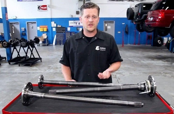
CROMOLIO: YUKON EJES Y DIFERENCIALES DE ALTO RENDIMIENTO LA CIENCIA DETRÁS DE LA FABRICACIÓN
Cromolio ... la pronunciación de la palabra son como imágenes provenientes de la fuerza de un superhéroe. La palabra se deriva del cromo y molibdeno, los dos principales elementos de aleación del metal. El cromo aporta tres beneficios principales como, dureza, un mejor mejoramiento de flexibilidad durante el proceso de enfriamiento y excelente resistencia a la corrosión. El molibdeno también sirve para aumentar la dureza de la aleación. Cuando se trata de ejes de alto rendimiento, el uso de cromoly da como resultado ejes que pueden manejar el estrés adicional que trae el uso de llantas más grandes o cuando se usan dispositivos de tracción más agresivos y otros parámetros como la agresividad con la que te metes al offroad. Su resistencia superior a una quebradura, la distorsión y la corrosión significa más tranquilidad en el sendero o en la pista de competición. En la fabricación de engranajes forjados, relaciones y ejes de alto rendimiento, juntas y más, Yukon utiliza 4340, una aleación de níquel-cromo-molibdeno de alta calidad. Mecanización de un Eje de Yukon La mayor parte del mecanizado en un eje se realiza antes del tratamiento térmico, pero algunas aplicaciones tienen ese trabajo que se realiza después del tratamiento térmico. Los procedimientos típicos de mecanizado incluyen molienda pulido de los rodamientos o sellado de la superficies, formación de bridas y guías de rueda, perforación de orificios, fresado de orejas para clips de círculo completo, taladrado de orificios de las juntas U, balanceo, etc. La creación de estrías es el proceso de mecanizado más importante en la fabricación de ejes. Como dice un dicho en inglés aquí “hay muchas formas de despellejar a un gato”. El método de corte que incluye fresado de las estrías, brochado rotativo, máquinas de balanceo y corte de disco es una parte de la ecuación. Luego está el método de laminado de las estrías que utiliza maquinaria CNC para formar las estrías mediante el desplazamiento de metal, no como la eliminación de metal que se encuentra en los procesos de corte. Yukon en casi todas sus aplicaciones de ejes mecaniza sus estrías mediante un perfilado en frío. Al igual que los principios de forjado, el eje está sujeto a una gran presión a través de herramientas en la máquina que contiene las estrías, tanto la forma como el número determinados por las especificaciones de diseño. En solo unas pocas revoluciones, las matrices de herramientas en forma de leva imprimen estrías en el eje. Esta es la mejor y más avanzada forma de hacer estrías y las ventajas de este proceso son muchas. La alta presión que envuelve en la creación de las estrías, reordena la estructura de grano del metal en todo el perfil del diente. Esto asegura una dureza constante en todo el eje y los dientes estriados. Además, la magia ocurre cuando está a temperatura ambiente, por lo que el producto final mantiene su resistencia a la tracción y dureza, tiene un mayor rendimiento y el proceso produce un acabado superficial superior en comparación con los métodos que cortan o extruyen las estrías. Este nivel de atención a los detalles da como resultado un eje con el que puede contar en los terrenos más difíciles. La fabricación y resistencia Los ejes originales están fabricados de aleaciones de carbono 1039, 1050 o 1055 y, en algunos casos, acero de la serie 1541 que es forjado y es tratado térmicamente o es endurecido Cómo llamar a este proceso de fortalecimiento es reducido a la semántica ... se puede llamar tratamiento térmico o tratamiento de endurecimiento porque el tratamiento térmico es el procedimiento y el endurecimiento es el resultado ... piense en la causa y el efecto. El cromoly es un metal dinámicamente más fuerte que las aleaciones de la serie 1000 y, dado que uno se comienza con un tratamiento aleación térmico superior, solo mejora el material. El objetivo es alterar las propiedades del metal a nivel molecular, produciendo una estructura de grano más apretada que cambia la dureza, resistencia, tenacidad, ductilidad y elasticidad del material de una manera beneficiosa. Tipos de endurecimiento / tratamiento térmico Hay dos tipos generales de endurecimiento: Cementación y templado. El endurecimiento por cementación solo trata la capa superficial mientras que el endurecimiento templado penetra hasta el centro del material. El endurecimiento templado se lleva a cabo en un horno donde el calor intenso tiene tiempo de penetrar en el núcleo del metal. Existe una serie de métodos para el endurecimiento de la carcasa, que es la técnica de tratamiento térmico más popular para los ejes originales y de alto rendimiento. Endurecimiento por inducción Este tipo de endurecimiento ha sido popularizado por los fabricantes de los equipos originales. El endurecimiento por inducción es rápido, económico, efectivo y controlable. La rapidez es debido al no tener que calentar todo el componente hasta su núcleo. Con esa velocidad se podrá contar con ahorros ya que se pueden tratar más ejes en un período de tiempo determinado, lo que reduce el costo total de tratamiento por eje. La eficacia es la producción de una pieza con una superficie resistente al desgaste pero que mantiene la dureza y la fuerza de su núcleo. Controlable porque el proceso se puede utilizar para endurecer selectivamente áreas de un componente sin afectar las propiedades de toda la pieza. Por ejemplo, algunos ejes originales solo se endurecen por inducción hasta la superficie de montaje cerca de la brida de apoyo. El endurecimiento por inducción es el método que Yukon utiliza en toda su línea de ejes de alto rendimiento. El proceso comienza con un eje que probablemente haya sido completamente mecanizado con estrías, etc. El eje se calienta con una inducción a una temperatura predeterminada generalmente entre 1,550 y 1,600 grados Fahrenheit y luego se apaga. El temple consiste básicamente en rociar la pieza con agua o dejarla caer en un baño de aceite para enfriar rápidamente. Las personas de control de calidad de Yukon escogen lotes de ejes al azar y los prueban para asegurarse de que han recibido el tratamiento térmico adecuado y estén a la altura de los planos de ingeniería. Carburación La carburación es algo similar al endurecimiento por inducción pero cambia / mejora las propiedades mecánicas del material al introducir un nuevo componente. Las bobinas de inducción u otros elementos calefactores llevan el metal a una temperatura alta. Luego, el sustrato de acero se expone a una fuente externa de carbono (gas, líquido o sólido) para formar carburos en la superficie del acero. Luego, el material se enfría para sellarlo. Endurecimiento de nitruro La nitruración es un juego con el método de carburación, excepto que se proporcionan sustancias portadoras de nitrógeno (amoníaco) en el sustrato en lugar de carbono. El proceso de recubrimiento de la superficie da como resultado la formación de nitruros sobre el sustrato de acero. Este particular proceso de cementación es específico de cromoly porque los nitruros solo se pueden crear en metales que contienen los elementos cromo y molibdeno. El endurecimiento con nitruro se diferencia de otras técnicas de cementación en que se utilizan temperaturas más bajas para calentar y el paso de temple es omitido por completo. Esto puede ser beneficioso porque menos calor y de un enfriamiento de un solo golpe producen menos distorsión en el producto final. Yukon no emplea este proceso porque la superficie infundida con nitruro no beneficia el rendimiento del eje, el proceso es caro y lleva más tiempo. Templado El templado se refiere a la repetición de un proceso de tratamiento térmico hasta que se alcanza la dureza deseada. Los beneficios del endurecimiento de los ejes El objetivo final del tratamiento térmico de un eje es crear una microestructura exterior dura y resistente a la abrasión mientras se conserva la resistencia a la tracción del acero dentro de su núcleo ... a prueba de balas si se quiere. El resultado es que un eje puede recibir golpes, soportar una gran cantidad de desgaste por fricción y también posee la resistencia a la torsión para absorber las fuerzas de torsión que se encuentran en situaciones de alta demanda de tracción. ¿Necesitas un eje fuerte y resistente en tu tren motriz? ¿Se toma en serio su conducción todoterreno, planea usar llantas más grandes, necesita reemplazar un eje y quiere lo mejor? Yukon hace un esfuerzo adicional en cada etapa del desarrollo del eje de cromoly; diseño, fabricación y control de calidad para que obtenga un eje que absorberá el abuso durante el offroad más extremo en los años venideros.
Subscribe To Our Newsletter
Sign up & unlock 5% off. Get news on insider deals, product releases, and expert advice.