
randys blog

Ford 9″ – Getting a ring to clear pilot housing
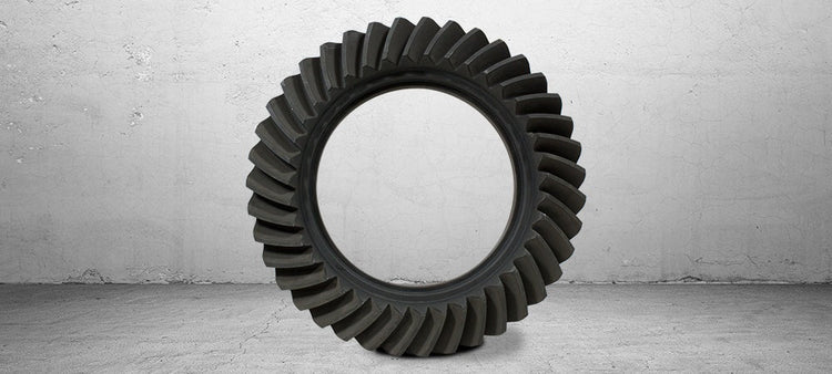
A very common problem when installing low gear ratios in a Ford 9” is that as the ring gear gets thicker the toe of the gear hits the pilot bearing housing leaving you with only two options, grind the gear, or the housing. We prefer grinding the gear, the problem with grinding on the pilot housing is it tends to make it thin and weak making it prone to cracking. By grinding the gear you have no sacrifice in strength and it takes less time. Some OE Ford gears as well as a small few aftermarket gear manufactures chamfer their gears from the factory to minimize the possibility of additional grinding being necessary during installation. Below is a picture of the best method we have found to clearance a 9” ring gear to clear the drop out case. CAUTION it is very easy to over heat the gear while grinding it with a bench top grinder, so be patient and only take as much as necessary. Clearing the pilot by 1/16” is more than enough clearance. After you have removed the necessary material, remove any burs with a 3M pad and thoroughly clean the gear before installation. Popular Resources: Ford 9 Inch Differential Information Four Critical Ring & Pinion Settings
Getting a cross pin shaft to clear a thick gear
In many cases it is necessary to grind one or more teeth on a ring gear in order to reinstall the cross pin in many c-clip style rearends. In most cases this will not interfere with the contact pattern of the gear or decrease the strength in any way as long as it is done properly. In some rare instances you may need to grind as much as ¼ of one or two teeth away. Although we have seen vehicles run with half of a ring gear or pinion tooth missing, we do NOT recommend pushing your luck that far. However, we have no problem running a gear-set in our own vehicles with 1/4 of tooth ground off of the toe or 1/8th of the heel of one or two of the ring gear teeth. Gear grinding should always be done on the bench top, not while gear is installed. This is to avoid getting metal and other contaminants into the housing or differential carrier. In most cases you will only need to grind about 1/8” off the corner of the tooth. After the desired amount of material is removed, you need to use a medium grit 3M disk to round the edges and remove any burrs. Be sure to clean a gear thoroughly before you reinstall it into the housing. Getting a cross pin shaft to clear a thick gear - In many cases it is necessary to grind one or more teeth on a ring gear in order to reinstall the cross pin in many c-clip style rearends. In most cases this will not interfere with the contact pattern of the gear or decrease the strength in any way as long as it is done properly. In some rare instances you may need to grind as much as ¼ of one or two teeth away. Although we have seen vehicles run with half of a ring gear or pinion tooth missing, we do NOT recommend pushing your luck that far. However, we have no problem running a gear-set in our own vehicles with 1 4 of tooth ground off of the toe or 1 8th of the heel of one or two of the ring gear teeth. Gear grinding should always be done on the bench top, not while gear is installed. This is to avoid getting metal and other contaminants into the housing or differential carrier. In most cases you will only need to grind about 1 8” off the corner of the tooth. After the desired amount of material is removed, you need to use a medium grit 3M disk to round the edges and remove any burrs. Be sure to clean a gear thoroughly before you reinstall it into the housing.
Properly setting preload with side adjusters
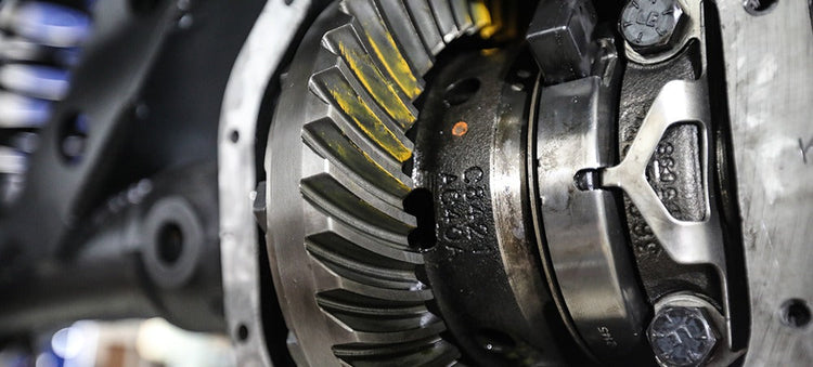
There are several types of rear ends that use a threaded side adjuster be it a single adjuster or one on both sides of carrier. The most commonly known rears with this type of carrier adjustment are the Chrysler 7.25-8.25-8.75-9.25, Ford 9”, GM 8.25” IFS, Suzuki Samurai, & Toyota. The GM 9.5” is a little different than most as one side uses shims but the other side is the threaded adjuster. Randy’s has tools that work with a 1/2” drive ratchet or breaker bar that work much better than beating the heck out of the adjuster with a punch & hammer. These side adjuster tools are priced starting at $29.00. Most people are reluctant to really crank on these adjusters to preload the carrier bearings. It is perfectly normal to have 150-200 ft lbs of torque on the side adjusters. It is very important to obtain good preload to avoid damage to your differential. At Randy’s, our service shop uses a 1/2” breaker bar, as shown in illustration 1A. The reason we do this is because as you accelerate, the pinion wants to make the ring gear deflect. The more power, the more it will tend deflect. Housings always flex, some more than others, depending on whether it’s stock or an aftermarket nodular. If you put a lot of preload on the carrier bearings it also preloads the housing. Since the housing is already flexed, it is not likely to flex even more causing the ring gear to move away from the pinion resulting in broken teeth. Properly setting preload with side adjusters - There are several types of rear ends that use a threaded side adjuster be it a single adjuster or one on both sides of carrier. The most commonly known rears with this type of carrier adjustment are the Chrysler 7.25-8.25-8.75-9.25, Ford 9”, GM 8.25” IFS, Suzuki Samurai, & Toyota. The GM 9.5” is a little different than most as one side uses shims but the other side is the threaded adjuster. Randy’s has tools that work with a 1 2” drive ratchet or breaker bar that work much better than beating the heck out of the adjuster with a punch & hammer. These side adjuster tools are priced starting at $29.00. Most people are reluctant to really crank on these adjusters to preload the carrier bearings. It is perfectly normal to have 150-200 ft lbs of torque on the side adjusters. It is very important to obtain good preload to avoid damage to your differential. At Randy’s, our service shop uses a 1 2” breaker bar, as shown in illustration 1A. The reason we do this is because as you accelerate, the pinion wants to make the ring gear deflect. The more power, the more it will tend deflect. Housings always flex, some more than others, depending on whether it’s stock or an aftermarket nodular. If you put a lot of preload on the carrier bearings it also preloads the housing. Since the housing is already flexed, it is not likely to flex even more causing the ring gear to move away from the pinion resulting in broken teeth.
New Gear Break-In
Do we really need to break in a new gear set? I have heard many people say “When I bought my new truck, no one ever told me to break in the ring & pinion.” Whenever we are blessed enough to afford a new vehicle, we take it easy on the engine for the first few hundred miles. While we are pampering the engine (probably for the last time ever), the ring & pinion set goes along for the ride and gets a chance to break in before we hammer the throttle. In most stock vehicles with stock tires there is seldom a risk of a burned gear set. For those of us who modify and use our trucks, there many situations that can contribute to burned gear syndrome. Motorhomes, towing, tall tires, and high numeric gear ratios (4.56 & up) can all generate a lot of heat and cause the gear oil to break down. The greatest damage to a new gear set results from running for ten minutes or more during the first 500 miles when the oil is very hot. Any heavy use or overloading while the oil is extremely hot will cause it to break down and allow irreversible damage to the ring & pinion. In order to make them run cooler and quieter, new gears are lapped at the factory. However, they are not lapped under the same pressures that driving creates. The loads generated while driving force any microscopic high spots on the gear teeth back into the surface of the metal. This is called “work hardening”. Work hardening is similar to forging in the way that it compresses the metal molecules into a very compact and hard formation. This can only be accomplished if the metal surfaces are lubricated and the gear temperature stays cool enough that the molecular structure does not change. If the temperature of the metal gets hot enough to change the molecular structure, it will soften the surface instead of hardening it. This may seen like a balancing act, but it all happens easily and passively as long as the oil keeps the gear cool while it is breaking in. Some of the synthetic oils on the market today can help a gear set live longer. I’ve had great success with Red Line ®, Torco ®, and Richmond Gear ® synthetic gear oils. These oils will continue to lubricate at temperatures where many crude oils break down. Even with synthetic oils, I still recommend the following procedure for breaking in a new gear set: After driving the first 15 to 20 miles, stop and let the differential cool before proceeding. Keep the vehicle at speeds below 60 mph for the first 100 miles. I also recommend putting at least 500 miles on the new gear set before heavy use or towing. During the first 45 miles of towing, it helps to go about 15 miles at a time before stopping to let the differential cool for 15 minutes before continuing. This is necessary because not all of the gear tooth is making contact until it is heavily loaded. When towing, the teeth flex to contact completely, and cause the previously unloaded portion of the teeth to touch and work harden. It is very easy to damage the ring & pinion by overloading before the teeth are broken-in. If you take it easy on a new ring & pinion and keep it full of high quality oil, it will last a lot longer. With regards to limited slip additives, I have found that using too much additive can lead to premature gear wear. Use just enough to keep the limited slip from chattering but not more than 4 oz for every 2 qts of oil. It is a good idea to change the gear oil after the first 500 miles in order to remove any metal particles or phosphorus coating that has come from the new gear set. This is cheap insurance and a good time to discover any problems before they grow too big.
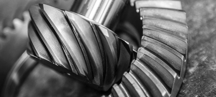
Grinding Gears
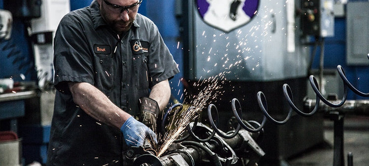
Many people would rather have their children genetically altered before they would grind gear teeth. Gears are not handed to us by God. They are designed by people who have figured out how to form steel into shapes that can be used to multiply torque and change power-shaft directions. Although some of us hold gears in very high esteem, they are not sacred. They can be ground on a surprising amount with little or no loss of strength. As long as the gears do not become hot (over 600 degrees) from the grinding, the molecular structure will remain the same and the hardness of the gear-set will not change. There are many situations where grinding gear teeth is not only OK, but can be helpful. Some of these include, but are not limited to: grinding to clear the cross-pin shaft, removing nicks from shipping with poor packing, rounding the corners on chips from a brittle surface, trimming the ring gear toe to clear 9″ Ford pilot bearing, chamfering the toe of the pinion teeth to clear the carrier case, smoothing high spots due to machining, or back-cutting race gears to allow for tooth bending. The drive side of the gear-set takes much more load than the coast side does and therefore it is a good idea to have a little restraint and think ahead before getting carried away on the drive side of a gear tooth. On the other hand, the coast side of the tooth gets loaded very little and not very often so it can take a huge amount of grinding with no negative side effects. Although I have seen vehicle run with half of a ring gear or pinion tooth missing, I do NOT recommend pushing your luck that far. However, I have no problem running a gear-set in my own vehicle with 1/4 of tooth ground off of the toe of one or two ring gear or pinion teeth. If the same 1/4 of the tooth was removed from the heel, I would be wary. I would not recommend removing more than about a 1/5 of the tooth from the heel of ring gear, because most of the load is from the center of the tooth to the heel when under load. And, it is the heel of the tooth that receives the hardest load. The pinion is another thing entirely. The last 1/4″ to 3/8″ of the pinion gear teeth do not even come close to touching the ring gear teeth on the drive side and therefore the tip can be removed entirely if the tooth or teeth are chipped, dinged, or damaged in any way. This heel portion of the pinion teeth often gets damaged in production or shipping and bothers people who are unfamiliar with rear end gears. If any part of the tooth does not contact other teeth, it can be removed without strength problems. In order to improve my confidence when attacking a new gear set, I often practice on an old gear set right before I approach the new set. This helps me pick the right cutting tool, set the angle of attack, and find the best cutter speed before I begin. The main thing to remember when grinding gears is to make sure that all corners are chamfered and there are no sharp edges to cut into the other teeth.