randys blog

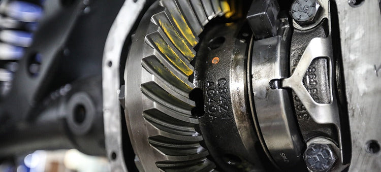
Getting a cross pin shaft to clear a thick gear
In many cases it is necessary to grind one or more teeth on a ring gear in order to reinstall the cross pin in many c-clip style rearends. In most cases this will not interfere with the contact pattern of the gear or decrease the strength in any way as long as it is done properly. In some rare instances you may need to grind as much as ¼ of one or two teeth away. Although we have seen vehicles run with half of a ring gear or pinion tooth missing, we do NOT recommend pushing your luck that far. However, we have no problem running a gear-set in our own vehicles with 1/4 of tooth ground off of the toe or 1/8th of the heel of one or two of the ring gear teeth. Gear grinding should always be done on the bench top, not while gear is installed. This is to avoid getting metal and other contaminants into the housing or differential carrier. In most cases you will only need to grind about 1/8” off the corner of the tooth. After the desired amount of material is removed, you need to use a medium grit 3M disk to round the edges and remove any burrs. Be sure to clean a gear thoroughly before you reinstall it into the housing. Getting a cross pin shaft to clear a thick gear - In many cases it is necessary to grind one or more teeth on a ring gear in order to reinstall the cross pin in many c-clip style rearends. In most cases this will not interfere with the contact pattern of the gear or decrease the strength in any way as long as it is done properly. In some rare instances you may need to grind as much as ¼ of one or two teeth away. Although we have seen vehicles run with half of a ring gear or pinion tooth missing, we do NOT recommend pushing your luck that far. However, we have no problem running a gear-set in our own vehicles with 1 4 of tooth ground off of the toe or 1 8th of the heel of one or two of the ring gear teeth. Gear grinding should always be done on the bench top, not while gear is installed. This is to avoid getting metal and other contaminants into the housing or differential carrier. In most cases you will only need to grind about 1 8” off the corner of the tooth. After the desired amount of material is removed, you need to use a medium grit 3M disk to round the edges and remove any burrs. Be sure to clean a gear thoroughly before you reinstall it into the housing.
Properly setting preload with side adjusters
There are several types of rear ends that use a threaded side adjuster be it a single adjuster or one on both sides of carrier. The most commonly known rears with this type of carrier adjustment are the Chrysler 7.25-8.25-8.75-9.25, Ford 9”, GM 8.25” IFS, Suzuki Samurai, & Toyota. The GM 9.5” is a little different than most as one side uses shims but the other side is the threaded adjuster. Randy’s has tools that work with a 1/2” drive ratchet or breaker bar that work much better than beating the heck out of the adjuster with a punch & hammer. These side adjuster tools are priced starting at $29.00. Most people are reluctant to really crank on these adjusters to preload the carrier bearings. It is perfectly normal to have 150-200 ft lbs of torque on the side adjusters. It is very important to obtain good preload to avoid damage to your differential. At Randy’s, our service shop uses a 1/2” breaker bar, as shown in illustration 1A. The reason we do this is because as you accelerate, the pinion wants to make the ring gear deflect. The more power, the more it will tend deflect. Housings always flex, some more than others, depending on whether it’s stock or an aftermarket nodular. If you put a lot of preload on the carrier bearings it also preloads the housing. Since the housing is already flexed, it is not likely to flex even more causing the ring gear to move away from the pinion resulting in broken teeth. Properly setting preload with side adjusters - There are several types of rear ends that use a threaded side adjuster be it a single adjuster or one on both sides of carrier. The most commonly known rears with this type of carrier adjustment are the Chrysler 7.25-8.25-8.75-9.25, Ford 9”, GM 8.25” IFS, Suzuki Samurai, & Toyota. The GM 9.5” is a little different than most as one side uses shims but the other side is the threaded adjuster. Randy’s has tools that work with a 1 2” drive ratchet or breaker bar that work much better than beating the heck out of the adjuster with a punch & hammer. These side adjuster tools are priced starting at $29.00. Most people are reluctant to really crank on these adjusters to preload the carrier bearings. It is perfectly normal to have 150-200 ft lbs of torque on the side adjusters. It is very important to obtain good preload to avoid damage to your differential. At Randy’s, our service shop uses a 1 2” breaker bar, as shown in illustration 1A. The reason we do this is because as you accelerate, the pinion wants to make the ring gear deflect. The more power, the more it will tend deflect. Housings always flex, some more than others, depending on whether it’s stock or an aftermarket nodular. If you put a lot of preload on the carrier bearings it also preloads the housing. Since the housing is already flexed, it is not likely to flex even more causing the ring gear to move away from the pinion resulting in broken teeth.

Installation: Spartan Locker Walkthrough
Unboxing: Front Axle (ZA)
Unboxing: Spartan Locker
Subscribe To Our Newsletter
Sign up & unlock 5% off. Get news on insider deals, product releases, and expert advice.