randys blog

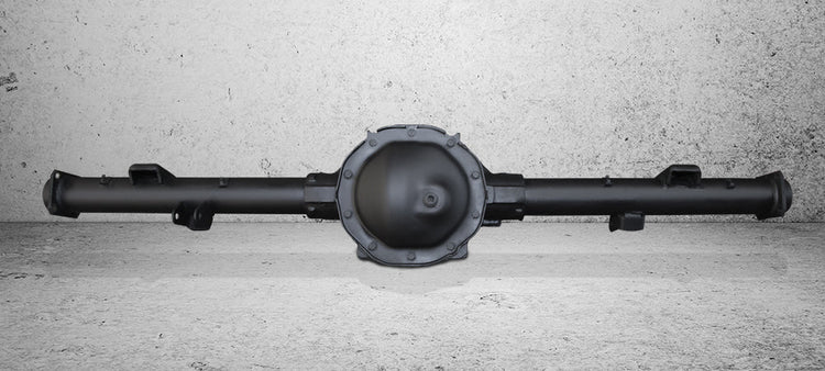
How It Works: Dropout Vs. Carrier-Type Differentials
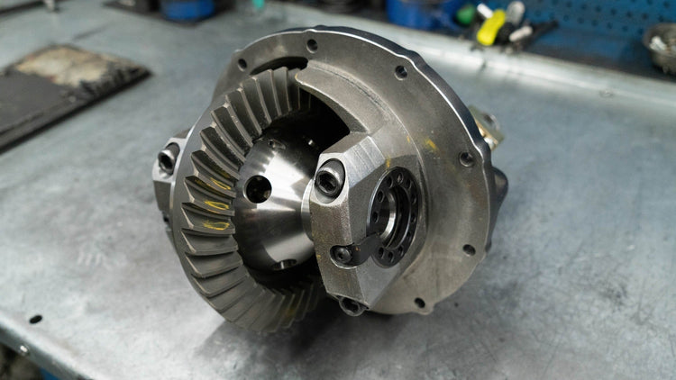
A pumpkin is a pumpkin, right? We’re talking about differential housings not jack-o’-lanterns; and hold your horses all are not created equal in the eyes of the drivetrain gods. While diff housings all do the same basic thing: house the gears that make forward motion possible, there are two different designs at work here. Dropout Differentials Dropout differentials, also known as third members, can be readily identified by their removable front center section. The ring and pinion gear set in a dropout diff is contained within a carrier assembly that can be removed or dropped out for easy access. The iconic Ford 9-inch is a dropout or third member type of differential and GM, Toyota, and Chrysler also offer dropout diffs. The ribbed housing is a quick giveaway that this is a Ford 9-inch. Along with the OE Ford 9-inch, there are tons of custom aftermarket Ford 9-inch configurations. The General has dropouts but many of them date back to the 1950s and are not relevant today. Toyota dropout-style diffs consist of the 7.5” rear, 8” rear, 8” high pinion, 8” clamshell, 7.5”, 8.5”, T100 IFS, and numerous 9”, 9.5”, and 10” offerings. In the Mopar world dropout differentials are called banjo-style diffs because someone thought the assembly, when pictured with an axle shaft, had the look of the infamous stringed musical instrument. The Chrysler 8.75” is the automaker’s most popular dropout-style diff. Of course, Dana manufactures a number of dropout style diffs that appear in vehicles across numerous brands. In some circles a front-loading dropout-type diff is known as a pig-style diff. While on the subject of slang, our friends across the pond call the ring gear a “crown wheel” … hey, as long as we’re on the same page it’s all good. Perhaps the main inherent advantage of a dropout diff is easy gear swaps. The gear swap advantage boils down to where you do the work. Since the gear case center section can be unbolted and removed, all the ring and pinion gear installation and tedious setup can be done away from the vehicle on a workbench. It’s more comfortable and access to, and applying leverage on, the key components is much easier. Carrier Differentials Carrier differentials have a cover on the backside of the pumpkin that is unbolted to gain access to the ring and pinion gears and other internal workings of the diff. GM’s 10-bolt and 12-bolt differentials are common examples of carrier-style diffs, which may be referred to as Salisbury differentials by those who speak the Queen’s English. The fact that the gears are visible on the backside of the housing is a telltale sign this is a carrier-type differential. Carrier-type differentials are more popular and they have some strengths when compared to a dropout diff. Troubleshooting is one. Looking for broken or worn parts in a carrier diff is as easy as removing the back cover where in a dropout you have to commit to a full gear case removal to see what’s going on. It should be noted that some custom aftermarket dropout diffs have rear inspection covers to address this concern. There is a less common concern for carrier diff drivers who wheel on the weekends; the diff cover. Traversing craggy terrain can result in the stock diff cover being peeled back like a can of sardines. A protruding rock or tree stump can also spell doom by way of impact damage. The answer: Yukon Hardcore Performance Diff Covers. They look great and are constructed from thick-walled high strength nodular steel to protect lockers, gears, and axles from extreme impacts as well as deflection caused by flex in the housing. Hardcore Performance Diff Covers come with a durable powder coat finish, magnetic drain plug, quality gasket, and high-strength steel fasteners for easy bolt-on installation. Knowing what dropout and carrier-type differentials are and a general idea how they work will help you make more informed installation decisions as you have the knowledge and vocabulary to talk straight with your mechanic. Shop Re-Gear Kits
Diagnosing Noise (Part 1)
Many things can go wrong inside a differential. Although the hints are often subtle, most impending failures give fair warning in the form of noise. Several situations can create ring-and-pinion noise. If the gears have been quiet and begin to howl, they are probably worn or wearing. If the gears howl during deceleration only, it’s possible that the pinion-bearing preload has loosened. Howling under acceleration at all speeds indicates that something in the differential — gears, pinion or carrier bearings — has worn or no longer keeps the gear alignment correct. If the gears howl while accelerating over a certain speed range, but not all speeds, it’s likely that the gears are worn due to lubrication failure or overloading. When a newly installed gear set howls, suspect the design or setup. A common problem is worn carrier bearings, as indicated by a low-pitch rumble above 20 mph. On vehicles with C-clip axles, the noise may vary while negotiating turns. Worn pinion bearings can cause whirring noises at all speeds, under deceleration and/or acceleration. Pinion bearings tend to whir, rather than rumble, because the pinion is turning several times faster (depending on gear ratio) than the carrier. Badly worn bearings can also cause howl if they do not support the gears correctly. Worn wheel bearings can be difficult to determine. A very bad wheel bearing typically makes itself heard with great clarity; it’s the bearing that is going bad, but not destroyed, that is hard to find. Turning back and forth from hard right to hard left can identify the culprit; however, I’ve been fooled by right-front wheel bearings that make noise when turning right (which heavily loads the inside-left-front wheel bearing, but also loads the outside-right-front bearing). One common situation that may not make any noise: The pinion spins, but the tires don’t rotate. Broken spider gears can render the differential immobile, and usually make a loud, crunching sound as they make their final departure. A broken ring gear will allow the differential to propel the vehicle for about eight feet at a time, then bang or grind as the section with broken teeth tries to engage the pinion. Depending on ratio, a broken pinion tooth (or teeth) will clunk about every two or three feet. A broken axle is easily determined. After it breaks, a C-clip design axle can be pulled out of the housing without unbolting anything — or may even find its own way out. On many bolt-in-design axles, the wheel will give the broken axle shaft away by cambering in at an angle. A high spot on a gear tooth may sound similar to a broken gear, but will only make noise while accelerating or decelerating, since the spot appears on just one side of the offending tooth. A high spot on the ring gear will make a heavy clicking sound about every eight feet; a high spot on the pinion makes noise every two or three feet and is much more pronounced due to its higher frequency. Whether large or small, differential noise is telling you something. Listen carefully! If in doubt, pull off the cover or remove the third member for a closer look. Catching a bad part before is ruins others is definitely worth the effort. Popular Resources: New Gear Break-In Properly Setting Preload with Side Adjusters Size Matters
WATCH: Lexus GX550 vs 6th Gen 4Runner Head to Head
What happens when ICON engineer & co‑founder Dylan Evans sets up the Lexus GX 550 and 6th Generation Toyota 4Runner up on the lifts and pits them side by side? In this breakdown, Dylan looks at the shared body-on-frame architecture, then reveals how each vehicle diverges in design, suspension tuning, performance, and purpose. Find out some of the ways where the GX and 4Runner share DNA...and where they split. Whether you prefer the triple‑row leather and high‑tech features of the Lexus or the trail-tested 4Runner ergonomics, here's your peek under the surface of these popular new platforms. Check out the video below!
ICON's Latest Video: 6th Gen 4Runner Skid Plate System
Protect What Matters Most: ICON Skid Plates for the 2025 Toyota 4Runner ICON Vehicle Dynamics introduces our all-new Skid Plates, purpose-built to defend your 2025 Toyota 4Runner’s most critical underbody components from trail damage and debris. In this video, ICON's Scott Spiva gives you a complete walkthrough of these premium upgrades, highlighting how they integrate seamlessly with your vehicle’s factory setup for a clean, bolt-on installation with no drilling, cutting, or welding required. Whether you're crawling through rocks or navigating rugged trails, ICON skid plates are engineered to take the hit so your drivetrain doesn't have to. Check out the video below!

Tales From The Tech Line: Picking Ratios… A Jeep JK Re-Gearing Story
Customer Question: Can you advise on a recommended gear ratio for a 2017 Jeep Wrangler four-door with a 3.6-liter motor running 35 inch tires? … Would it be 4.56 or 4.88? Gus: Is it an automatic or manual transmission? How will it be used? Customer: Automatic. It’s a daily driver and weekend warrior off-roader. I do some off-road driving for my job during the week. I’m running 3.73s currently. Gus: The 3.6-liter finds its happy place cruising in the 2,000 to 2,500 rpm range, they aren’t really known for bottom-end torque. Check the graph above.
Subscribe To Our Newsletter
Sign up & unlock 5% off. Get news on insider deals, product releases, and expert advice.