
randys blog

Common Carrier Breaks
As discussed in detail last month, there are many situations where a different height carrier case is needed when making a gear ratio change. Included here is a list of carrier breaks for most popular rearends. Many of these have thick or thin ring & pinion sets available to eliminate the need for changing carriers. Rearends with those options available for some ratios are indicated in the chart below. Now you have the chance to memorize them all and impress your friends. There is really no magic formula the original equipment manufactures uses to decide the actual breaking point for each design. It depends on the placement of the carrier case and the pinion centerline, and those are really arbitrary and up to the whim of a design engineer. As mentioned last month, I do NOT recommend ring gear spacers in any situation. Remember that using a thick or thin gear set has no side effects and will be just as strong and hold up just as well as a gear set that is the factory thickness. AMC M35 3.31 & down / 3.55 & up (a.k.a. Dana 35. Some early models used a thin 3.08 that only fits the 3.55 & up case) M20 2.73 & down / 3.07 & up General Motors Cast Iron Corvette 3.90 & down / 4.10 & up D36 ICA 2.73 & down / 3.07 & up D44 ICA 3.73 & down / 3.92 & up 55-64 Chevy passenger 3.70 & down / 4.10 & up (some came stock with thin or thick gears) 55-62 Chevy 1/2 ton all use same height carrier Early Olds Drop-out 3.23 & down / 3.55 & up 7.2″ IFS 3.08 & down / 3.23 & up 7.5″ 3.08 & down / 3.23 & up 7.75″ 2.77 & down / 3.27 & up 8.2″ Chevy 2.76 & down / 3.07 & up 8.2″ BOP 2.76 & down / 2.94 to 3.23 / 3.31 & up 8.25″ IFS all use same height carrier 8.5″ 2.56 & down / 2.76 & up 9.25″ IFS all use same height carrier 9.5″ 14 Bolt all use same height carrier 12 Bolt Passenger 2.76 & down / 3.07 to 3.90 / 4.10 & up * 12 Bolt Truck 2.73 & down / 2.76 to 3.42 / 3.73 & up 10.5″ 14 Bolt 4.11 & down / 4.56 & up Ford Ford does not use any carrier brakes in any of their “corporate” rearends. Chrysler 7.25″ 2.47 & down / 2.76 & up 8.25″ 2.45 & down / 2.56 & up 8.75″ all use same carrier 9.25″ all use same carrier Dana Spicer D27 3.73 & down / 3.92 & up D28 3.45 & down / 3.73 & up D30 3.54 & down / 3.73 & up D44 3.73 & down / 3.92 & up D50 all use same height carrier D60 4.10 & down / 4.56 & up D61 3.31 & down / 3.54 to 4.10 with thick gear / 3.54 to 4.10 with regular gear D70-1/2″ & 5/8″ offset 4.10 & down / 4.56 & up D70-31/31″ offset 3.42 & down / 3.54 to 4.10 (4.56 & up will NOT fit this housing) D80 3.73 & down / 4.10 & up Toyota 7.5″ all use same height carrier 7.8″ (a.k.a. 8″) 3.73 & down / 3.90 & up The OEM Toyota gears of 4.88 and numerically higher ratio used a different carrier case or a spacer. Virtually all aftermarket gear sets made for this rear end are a thick version that does not require a spacer. V6 all use same height carrier. There is however a housing offset difference in vehicles factory equipped with a 4.88 ratio. Installing aftermarket gears in these vehicles requires changing the drop-out housing to a 4.56 & down design. The carrier case is the same height for both housing and can be interchanged if the appropriate housing is used. * Thin Available ** Thick Available Popular Resources: Ford 9 Inch Differential Information Four Critical Ring & Pinion Settings

Four Critical Ring & Pinion Settings
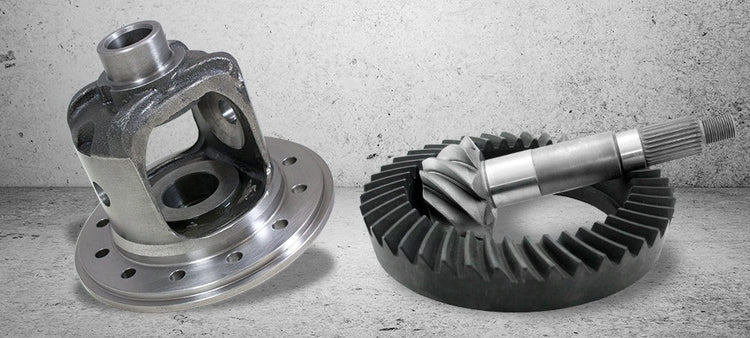
Although proper ring & pinion setup can be accomplished at home, I really recommend having a professional do the job. However, if a person really insists on trying it (and that is really the only way to learn), here is some information that should be helpful. When setting up a ring & pinion, there are four critical settings that need to be correct in order to get proper setup and good gear life. They are: Pinion depth (how close the pinion is to the ring gear), backlash (how close the ring gear is to the pinion), pinion bearing preload (how much bearing drag is on the pinion bearings), and carrier bearing preload (how much bearing drag is on the carrier bearings). Given enough time, just about any approach will work when setting up a ring & pinion. However, I suggest adjusting the four settings in the following order so that the job goes faster with less frustration. First, set the backlash using only light carrier bearing preload. The proper preload can be added closer to final assembly. Next, check the pinion depth by way of the contact pattern. Make sure you use only real gear marking compound (available from GM as part # 1052351), as other marking substances are difficult to read. There are many theories about how to read the contact pattern, but I won’t open that can of worms now. After checking the pattern, it is usually necessary to adjust the pinion depth. After changing the pinion depth, the pattern should be rechecked. The backlash may have to be readjusted as the pinion depth is changed. It should be close to specifications in order to get a good pattern reading. Once the correct pinion depth is established, the pinion bearing preload can be adjusted. When setting the pinion bearing preload on a crush sleeve design differential, it is always necessary to use a new crush sleeve every time the pinion nut is removed, or if the sleeve is over-crushed. When installing the carrier, the same adjusters or shims that are used to adjust the backlash are also used to set the carrier bearing preload. Rather than trying to change the backlash and preload at the same time, I recommend getting the backlash correct and then adding preload for the final assembly. If the carrier has to be moved to set the backlash, it is easier to remove if the preload is not too tight. Once the backlash has been set, the carrier bearing preload can be added. Some books give exact specifications of how much preload to add to the carrier bearings. I find that the given specs are not always easy to measure or achieve. If they call for 0.015″ preload, a zero point must first be established, and that is not easy either. I recommend setting the carrier bearing preload as tight as you can get it without damaging the shims during installation. For screw adjuster type differentials, I recommend about 100 to 150 ft lbs. of torque on the adjusters. From my experience, I have found it difficult to over preload the carrier bearings. I have only seen it done in a few cases, and those involved a mechanic with Schwarzenegger-like arms. Many people claim that setting the backlash too tight is good for high impact applications so that the backlash will not open up too wide. I have been guilty of this claim in the past; however, experience has shown me that it is lack of carrier bearing preload that causes the backlash to open up and not some magical transformation due to high shock loads. Now that these four settings are correct, the installation is almost complete. Remember to use good high quality oil and follow the manufacturer’s break-in procedure Popular Resources: New Gear Break-In Properly Setting Preload with Side Adjusters Size Matters
Fixing a chipped Pinion Gear
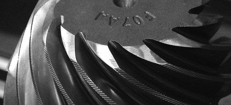
Some gear sets get chipped or nicked during the manufacturing process or during shipping. In most cases these blemishes are outside the contact pattern, and they can be removed with a few minutes of careful polishing. First thing is to determine if the nick is in the pattern. If this isn’t obvious by looking at the gear, you can install the set into the housing and run a quick pattern check. When you have determined that the chip or nick is clear of the pattern, use a medium grit 3M disk to polish out the nick. This is necessary to prevent any jagged edges from coming into contact with the gear under load and possibly causing damage. Popular Resources: Limited Slips: Gov-Lock vs. Yukon Dura Grip Identifying Borg Warner Transfer Cases Limited Slips vs. Differential Lockers vs. Spools

Ford 9″ – Getting a ring to clear pilot housing
A very common problem when installing low gear ratios in a Ford 9” is that as the ring gear gets thicker the toe of the gear hits the pilot bearing housing leaving you with only two options, grind the gear, or the housing. We prefer grinding the gear, the problem with grinding on the pilot housing is it tends to make it thin and weak making it prone to cracking. By grinding the gear you have no sacrifice in strength and it takes less time. Some OE Ford gears as well as a small few aftermarket gear manufactures chamfer their gears from the factory to minimize the possibility of additional grinding being necessary during installation. Below is a picture of the best method we have found to clearance a 9” ring gear to clear the drop out case. CAUTION it is very easy to over heat the gear while grinding it with a bench top grinder, so be patient and only take as much as necessary. Clearing the pilot by 1/16” is more than enough clearance. After you have removed the necessary material, remove any burs with a 3M pad and thoroughly clean the gear before installation. Popular Resources: Ford 9 Inch Differential Information Four Critical Ring & Pinion Settings

Ford 9″ – Fixing a damaged side adjuster
If you do a fair amount of differentials the odds are pretty good that you have come across a spun carrier bearing or two in you time. Most people think that this means you need to hunt for a new housing or drop out but that’s not the case in most instances. There are two different fixes for this problem depending on what style of housing your working on. It’s very common to find a Ford 9” that has a side adjuster with a grove warn into it from the carrier bearing race, the fix for this is very simple and takes just a few minutes. Using a 1 1/2”wide, fine flat file lay the adjuster flat on the bench then lay the file flat onto the adjuster and file the entire adjuster until the ridge is gone. Popular Resources: New Gear Break-In Properly Setting Preload with Side Adjusters Size Matters