randys blog


4WheelToHeal Charity T-Shirt Design Contest
In conjunction with ICON Vehicle Dynamics and Dynatrac, Yukon is supporting Trail Hero and 4WheelToHeal charities by hosting a T-shirt design contest with participants ranging in age from 4 to 15. 4WheelToHeal is a non-profit organization dedicated to serving wounded and disabled veterans of all branches of military service. Their mission is dedicated to taking wounded and disabled veterans/service members from all branches of the military to off-roading events. These events include: four wheeling, rock crawling, mud bogging, off-road racing, shooting, and camping. Our mission is to boost morale, introduce warriors to the fantastic off-road community and give them an experience they will never forget. A full 100% of donations goes toward supporting warrior events. All proceeds from the contest will go toward 4WheelToHeal and the winner will be given family swag packs from our brands as well as have the shirt for sale as the Trail Hero Charity Tee. Drawing submissions will be accepted from July 4th (Independence Day) to August 7th (Purple Heart Day). Click here for more information
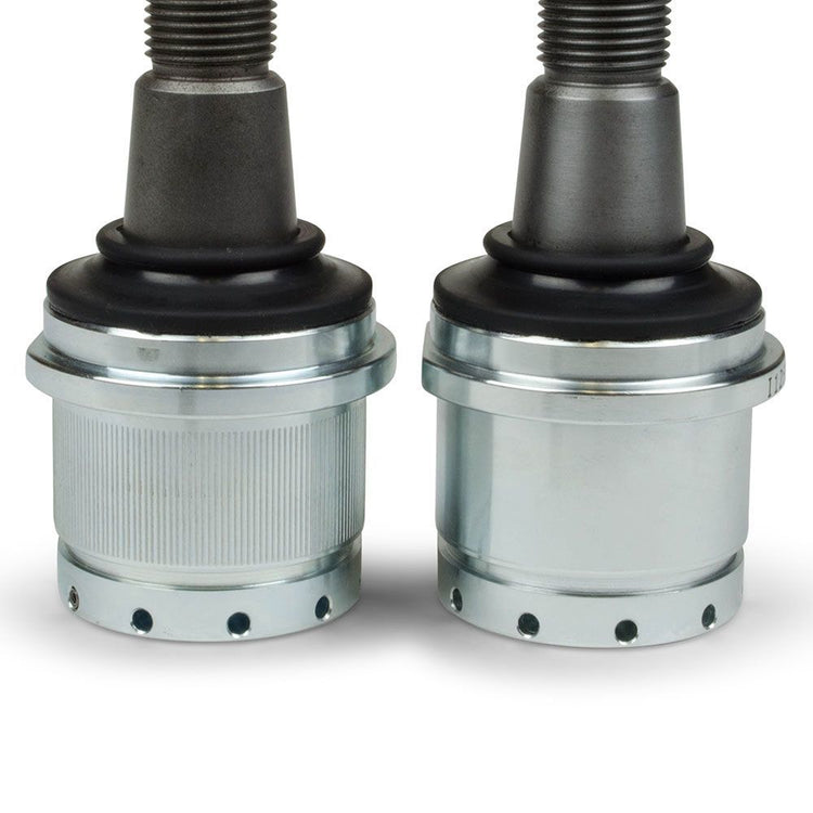
Knurled Or Smooth: Which Ball Joint Is Right For You?
First and foremost, knurled ball joints are a last resort not a first or better option. They are only to be used on suspensions that have knuckle bores and/or housing end forgings that are so worn they can no longer properly accept a smooth-body ball joint. A knurled ball joint has grooves machined into its body that serve to fatten the body, allowing the unit to press into an enlarged mounting space tightly. Bore wear can be trail abuse but usually means you have changed ball joints a number of times and the bore has succumbed to the pressure of being pressed in place. The result is those knuckle bores or end forgings have become enlarged or out of round such that a ball joint body which is the correct diameter may not fit. If you don't need the extra tightness we strongly recommend you don't use a knurled ball joint. Beware. We know that a lot of our competitors and many aftermarket service parts out there automatically come with knurled bodies. The problem is once you install a knurled ball joint you have no where to go when the knuckle bores or end forgings wear. If a knurled joint is your first service part you have sacrificed the future because you have willingly enlarged the bores and down the road you'll eventually get to a point where nothing fits. So only install a knurled ball joint because a normal smooth body unit will not press in tight enough. RANDYS offers ball joints from Yukon, Dynatrac, Carli Suspension, and ICON Vehicle Dynamics, and some applications feature both smooth and knurled body designs. Shop Ball Joints
How To: Spartan Locker Assembly
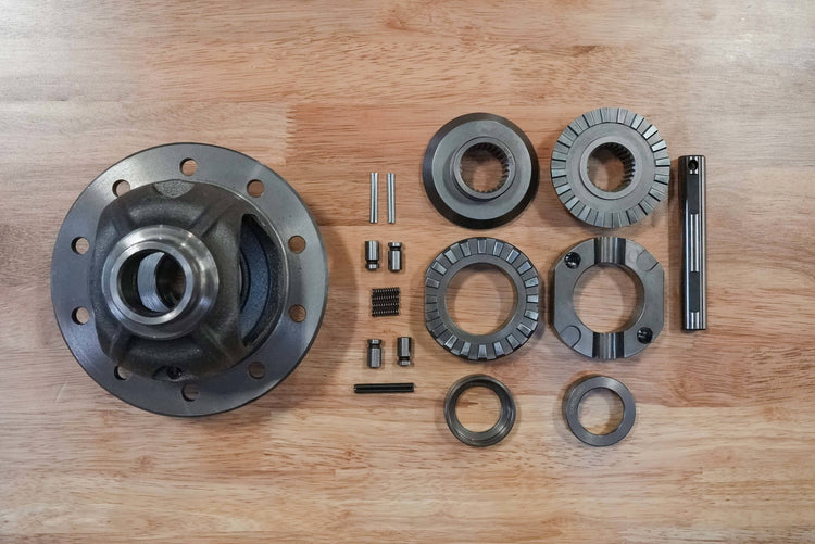
Lunchbox lockers provide reliable 100% lock-up traction at a low cost. The simplicity and ingenuity living within the Spartan Locker makes it better than conventional lunchbox lockers. The Spartan Locker’s patent-pending design replaces the spider gears in a standard carrier case without using the thrust washers, but the unit’s most revolutionary attribute is its spring-and-pin design. This characteristic makes assembly and installation straightforward and easy, as the carrier may not need to be removed in some instances. The Spartan Locker is the most DIY-friendly locker on the market and many experienced enthusiasts install the unit themselves versus taking their rig to a shop. Anatomy of a Spartan Locker Lunchbox lockers are not a singular component. They start as individual components that are assembled together and installed in an open differential carrier (and only an open differential carrier) to transform it into a mechanically locked diff. Generally speaking, Spartan Lockers include a pair of drivers, two spacers, two side couplers, four alignment pins, four pre-load springs, a hardened cross-pin shaft, a roll pin, and installation retaining wires. Shop Spartan Lockers Now Installation Tips & Tricks The Breakdown The installation process can take one of two paths: in the diff or on the workbench. It all begins with the breakdown. If your diff runs a numerically high gear ratio, like a 4.88 or 5.13, the thickness of the ring gear may make removal of the cross pin impossible with the carrier still in the diff. If this is the case… before proceeding to remove the carrier it is critical that you mark the bearing caps with a punch to denote which side of the diff each belongs on. Note, some diffs are pre-stamped, typically with a horizontal ‘H’ on one side and a vertical ‘H’ on the other. These correspond with markings on the bearing caps. Check your backlash with a dial indicator, save the measurement to ensure proper re-installation. Like the bearing caps, keep track of which side the shims and carrier races come out of. With everything arranged, the carrier can be pulled out and the ring gear can be removed from the carrier. At this point, the following steps apply whether you’re working with the diff still installed or on the bench. Remove the cross pin by punching out the roll pin and tapping the cross pin until it can be pulled out. Next, take out the sider gears and thrust washers. A tip here, rotate the gear set via the axle gears until the side gear presents itself for removal. Assembling Humpty To get the ball rolling place a spring into the hollow end of each of the alignment pins, and set them aside. Grab the drivers and install the four alignment pin and spring combinations into the respective driver holes. Push each alignment pin/spring assembly fully down into the driver, compressing the spring and insert the retaining wire into the retaining wire hole in the driver to maintain preload and keep the pin from popping out. This also creates a flush surface which aids in installation. Next, install side the couplers into the carrier case. Remember, DO NOT use thrust washers from previous setup. There is no top- or bottom-specific coupler. Each coupler should be positioned in the carrier with the teeth facing the center of the unit. Install the spacers into the centers of each driver, making sure that the “open” face of the spacer is positioned toward the driver’s teeth. It will be handy to put a dab of grease between the spacer and driver to keep them together as the installation proceeds. Take one of the center drivers, with the spacer placed in it, and install it into the carrier with its teeth surface facing the coupler’s teeth. Note, the retaining wire may need to be bent alongside the drivers to be properly installed in some carriers. Repeat this process for the remaining three alignment pin/spring assemblies as needed. Orient the drivers until the alignment pin/spring assemblies line up with their corresponding alignment pin seating notches in the opposite driver. On c-clip axle applications install the clips in their groove. Pull the retaining wires out of the alignment pin/spring assemblies using a suitable tool, allowing the alignment pin to extend fully into the seating notch in the opposite driver. Manipulate the two halves until you hear the unit snap into place or you are confident all the pins are fully engaged. Gap Insurance To ensure all the pieces are in working order a center gap measurement is needed. With the Spartan Locker components fully installed measure the distance between the two Spartan drivers using a set of feeler gauges or a slide caliper. The distance should measure between .145 and .170 inches. Measure at a few different spots around the circumference of the unit. If the measurement doesn’t fall within this range check for potential obstructions. Back Into The Diff With the assembled locker in the carrier, spin the unit until the cross pin shaft holes in the locker and the hole in the carrier line up so the cross pin can be installed properly. Be sure to keep the hole for the roll pin in alignment with the carrier roll pin hole. Install the cross pin and secure it by inserting the roll pin, which taps into place with a ball-peen hammer and a punch. Finally, re-assemble the driveline. We are illustrating this installation in a typical application. Installs in Ford 8-inch and 9-inch rear ends, Toyota V6 applications, and Suzuki Samurai are very similar and the USA Standard Gear installation manual outlines the minor differences to ensure a smooth install. Whether you plan to tackle the job yourself or farm it out to a driveline shop it’s important that you understand what is involved so at the very least you and your mechanic speak the same language. Happy wheeling. Popular Spartan Locker Applications Chrysler 8.25" with 29 spline axles, includes heavy-duty cross pin shaft SL-C8.25-29 Chrysler 8.25" with 27 spline axles, includes heavy-duty cross pin shaft SL C8.25-27 Nissan H233B Front with 31 Spline SL NPATROL-31 Nissan M226 Rear with 32 Spline SL NTITAN-32 Dana 30 Jeep JL M186 Differential SL D30JL-27 Dana 44HD differential with 30 spline axles, includes heavy-duty cross pin shaft SL D44HD-30 Dana 44 differential with 30 spline axles, includes heavy-duty cross pin shaft SL D44-30 Dana 44 differential with 19 spline axles, includes heavy-duty cross pin shaft SL D44-19 Dana 60 with 30 spline axles, includes heavy-duty cross pin shaft SL D60-30 Dana 60 differential with 35 spline axles, includes heavy-duty cross pin shaft SL D60-35 GM 12 bolt car & truck with 30 spline axles, includes heavy-duty cross pin shaft SL GM12-30 GM 8.5" with 28 spline axles, includes heavy-duty cross pin shaft SL GM8.5-28 GM 8.5" with 30 spline axles, includes heavy-duty cross pin shaft SL GM8.5-30 Suzuki Samurai differential with 26 spline axles SL SUZSAM Model 20 differential with 29 spline axles, includes heavy-duty cross pin shaft SL M20-29 Model 35 differential with 27 spline axles and a 1.560" carrier, includes heavy-duty cross pin SL M35-1.5-27 Toyota 8" differential with 30 spline axles, includes heavy-duty cross pin shaft SL T8-30 Toyota 7.5" with 27 spline axles, includes heavy-duty cross pin shaft SL T7.5-27 Toyota V6 with 30 spline axles SL TV6-30 Ford 8.8", 31 spline, includes heavy-duty cross pin shaft SL F8.8-31 Ford 9", 28 or 31 spline SL F9-28-31
The Ultimate Gear Break-In Guide: Ensuring Peak Performance and Longevity
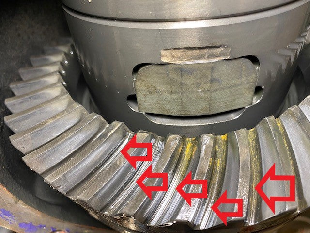
Gear break-in is a crucial process that involves controlled heat cycling of the gear set to properly season and harden the contact surfaces as well as to polish and establish the final contact pattern on the gear face. It is essentially a series of test drives that play a vital role in ensuring the long-term durability and optimal performance of the gears. Neglecting or improperly conducting the break-in procedure can lead to damaged or failing gears, necessitating a complete re-do of the installation. Even after the gear installation is completed, with correct backlash and preload settings, the break-in process is a make-it-or-break-it proposition. This involves driving the vehicle on urban roads and freeways, as different vehicle speed ranges induce varying levels of heat cycling. Additionally, if towing is part of your intended use, an additional round of break-in is necessary. Towing puts additional pressure on the pinion and slightly alters its position on the ring gear teeth. By subjecting the gears to this towing-induced stress during the break-in period, you effectively harden and condition the specific areas of the gear teeth that come into contact under towing conditions. Proper Gear Break-In: 5 Essential Steps Properly conducting the gear break-in process is of utmost importance, as it can make a significant difference between encountering gear-related issues down the line and enjoying trouble-free driving for years to come. By adhering to the recommended break-in procedures, including the specific requirements for towing, you ensure that the gears are thoroughly seasoned and hardened, promoting their longevity and reliability. To ensure the proper break-in of new gear sets and prevent overheating damage, it is crucial to follow these guidelines: 1) Drive light-footed at low speeds for the first 15 to 20 miles: Take it easy and baby the vehicle during the initial 15 to 20 miles. Afterward, stop and allow the differential to cool down before continuing. Repeat to 100 miles. 2) Avoid heavy acceleration: During the first 100 miles of the break-in period, avoid any sudden or extreme acceleration and steep hills, as this can put excessive stress on the gears. 3) Change the gear oil after the first 500 miles: After driving approximately 500 miles, it is advisable to change the gear oil. This helps remove any metal particles or phosphoric coating that may have been shed by the gear set during the break-in period. 4) Drive at least 500 miles before towing: To retain the warranty on the gears, it is recommended to drive the vehicle for a minimum of 500 miles before towing any heavy loads. 5) Break in the gears when towing for the first time: If you need to tow a load for the first time, follow this procedure: Drive a very short distance (less than 15 miles) with the full load, then stop. Allow the differential to cool for approximately 20 minutes before proceeding. Repeat this process two more times, covering a total distance of approximately 45 miles, to fully break in the gears. By adhering to these guidelines, you can ensure a proper break-in of your new gear sets and minimize the risk of overheating damage. It's important to follow these recommendations to maintain the warranty on the gears and promote their longevity and optimal performance. How Hot is Hot? We’re not talking about judging the temperature by touch. Most people find it difficult to hold a cup of coffee that is at 140°F, and a shower at 120°F can cause scalding. To obtain more precise temperature readings, we recommend using a handheld infrared digital thermometer, which can be purchased for $15 to $50 at most any auto parts store. By using this tool, you can determine the temperature more accurately and refer to the chart below to determine the appropriate oil change interval. During the break-in period, it is normal for new differentials to run at temperatures ranging from 250°F to 275°F. It is crucial to avoid towing or embarking on long road trips during the first 500 miles, as these activities generate additional heat. If the differential reaches a temperature of 300°F, it is considered too hot, and it should be allowed to cool down. Once the break-in period is completed, the normal operating temperature for a differential in a vehicle with stock trim and regular driving conditions is between 170°F to 220°F. However, for vehicles equipped with large tires, undersized differentials, or engaged in towing, the normal operating temperature ranges from 200°F to 250°F. Remember that a new gear break-in requires an oil change at 500 miles to ensure optimal performance and longevity of the differential. Use your findings in the chart below to determine your oil change interval. Temp Reference / Oil Change Frequency Chart TEMPERATURE FREQUENCY 170° 100,000 Miles 200° 50,000 Miles 220° 25,000 Miles 240° 12,000 Miles 260° 5,000 Miles 260°-320° 500-1,000 Miles [until temp is controlled] Mistreated & Overheated: How Improper Gear Break-In Kills Your Gears When examining the accompanying images of mistreated and overheated gears, several key factors come into focus. One of the most significant is the process of gear meshing during a correct break-in procedure. As temperature rises and pressure is applied, these forces work to harden and compress the grain structure, effectively smoothing the surfaces of the gear teeth. However, in the images provided, the teeth appear coarse and exhibit an exposed grain structure, indicating insufficient break-in. Another crucial but often overlooked aspect is the role of the oil in the cooling down process, known as "quenching" the gears. Similar to the technique used in knife making, where super-heated metal is rapidly cooled in an oil bath, this process alters the surface metallurgy of the gears. However, in gear break-in, we aim to avoid extreme heat like that used in knife manufacturing. This heating and cooling cycle is repeated during the drive cycles of the break-in period, contributing to the gear's overall durability. Breaking in deep gears on a small differential can be challenging due to reduced contact area and less metal in the pinion head to act as a heatsink. Excessive heat during the break-in period can also cause the hard face built up through initial break-in to peel away under gear meshing, leading to changes in backlash. This fracture and peeling off of the hard face exposes a rough grain structure, essentially reverting the metal back to its pre-break-in condition. Subsequently, the gear break-in process restarts with even rougher gears, creating a downward spiral. Additionally, gear geometry is altered as the teeth become thinner and smaller, further exacerbating the issue. While adjusting backlash may address one variable, it fails to address the underlying problem. The burnt ring gear pictured above shows the telltale signs of heat damage due to improper break-in: Coarse grain structure (red ovals) on the teeth where there should be a mirror-like finish and fracturing across the face (yellow arrows). Another frequently disregarded concern is the cooling airflow from underneath the vehicle. At highway speeds, the airflow around the differential can become stagnant. Surprisingly, overheating gear sets often result not from actual overloading but from driving at high speeds for extended periods too early in the break-in process. Light throttle cruising at freeway speeds, although seemingly gentle on the parts, can generate more heat than the differential can dissipate. This particular scenario accounts for a significant number of gear set failures during the break-in phase. Based on these observations, it is recommended to use a quality 80-90 GL5-rated conventional gear oil during the break-in period. If there is a suspicion of overheating, changing the oil is advisable since conventional gear oil is relatively inexpensive. It's essential to remember that differentials lack internal filtration, making regular draining, cleaning, and refilling necessary to remove wear particles. Additionally, conventional gear oil possesses distinct properties that facilitate effective gear "quenching," maintaining viscosity better and adhering to parts more effectively compared to synthetic oils. In conclusion, proper gear break-in is a critical to carefree motoring. By following these guidelines and understanding the intricacies of gear break-in, owners can ensure the longevity, reliability, and performance of their gears, mitigating the risks associated with improper break-in practices. Shop Ring and Pinion Sets
Check Your Shipment… Count Your Teeth
Before proceeding with your drivetrain project, it is essential to check your shipment to ensure that everything is in order. Conducting a thorough inspection helps identify any potential issues, verify the contents, and address any discrepancies or damage. As always, check the contents against the packing slip or order. Review the packing slip, invoice, or order confirmation to ensure all items are included and in the correct quantities. But with all that’s involved with drivetrain jobs, especially ring and pinion gear swaps/replacements, it’s wise to go one step further and confirm the gear ratio is correct by calculating it the old school way. Count the number of teeth on both the ring gear and the pinion gear. The number of teeth may be marked or engraved on the gears themselves but do the by-hand calculation to be sure. Divide the number of teeth on the ring gear by the number of teeth on the pinion gear. This calculation will give you the gear ratio. For example, if the ring gear has 41 teeth and the pinion gear has 10 teeth, the gear ratio would be 4.1 which simplifies to 4.10. 41 ÷ 10 = 4.1 The resulting gear ratio represents the number of revolutions the pinion gear will make for each revolution of the ring gear. For instance, in the example above, the pinion gear would rotate 4.10 times for every single rotation of the ring gear. Keep in mind that the gear ratio can be expressed in different formats. It can be written as a decimal (e.g., 4.10), as a fraction (e.g., 4.10:1), or as a percentage (e.g., 410%). The specific format may vary depending on the industry or application. Installing the wrong/mismatched gear is a nightmare, whether by confusion in the shop or mis-shipped products, because getting this wrong can be embarrassing and necessitates the complete re-rebuild of the diff. Further, having to start over from square one takes up valuable time and shop supplies.
Subscribe To Our Newsletter
Sign up & unlock 5% off. Get news on insider deals, product releases, and expert advice.