randys blog

Diagnosing Noise (Part 1)
Many things can go wrong inside a differential. Although the hints are often subtle, most impending failures give fair warning in the form of noise. Several situations can create ring-and-pinion noise. If the gears have been quiet and begin to howl, they are probably worn or wearing. If the gears howl during deceleration only, it’s possible that the pinion-bearing preload has loosened. Howling under acceleration at all speeds indicates that something in the differential — gears, pinion or carrier bearings — has worn or no longer keeps the gear alignment correct. If the gears howl while accelerating over a certain speed range, but not all speeds, it’s likely that the gears are worn due to lubrication failure or overloading. When a newly installed gear set howls, suspect the design or setup. A common problem is worn carrier bearings, as indicated by a low-pitch rumble above 20 mph. On vehicles with C-clip axles, the noise may vary while negotiating turns. Worn pinion bearings can cause whirring noises at all speeds, under deceleration and/or acceleration. Pinion bearings tend to whir, rather than rumble, because the pinion is turning several times faster (depending on gear ratio) than the carrier. Badly worn bearings can also cause howl if they do not support the gears correctly. Worn wheel bearings can be difficult to determine. A very bad wheel bearing typically makes itself heard with great clarity; it’s the bearing that is going bad, but not destroyed, that is hard to find. Turning back and forth from hard right to hard left can identify the culprit; however, I’ve been fooled by right-front wheel bearings that make noise when turning right (which heavily loads the inside-left-front wheel bearing, but also loads the outside-right-front bearing). One common situation that may not make any noise: The pinion spins, but the tires don’t rotate. Broken spider gears can render the differential immobile, and usually make a loud, crunching sound as they make their final departure. A broken ring gear will allow the differential to propel the vehicle for about eight feet at a time, then bang or grind as the section with broken teeth tries to engage the pinion. Depending on ratio, a broken pinion tooth (or teeth) will clunk about every two or three feet. A broken axle is easily determined. After it breaks, a C-clip design axle can be pulled out of the housing without unbolting anything — or may even find its own way out. On many bolt-in-design axles, the wheel will give the broken axle shaft away by cambering in at an angle. A high spot on a gear tooth may sound similar to a broken gear, but will only make noise while accelerating or decelerating, since the spot appears on just one side of the offending tooth. A high spot on the ring gear will make a heavy clicking sound about every eight feet; a high spot on the pinion makes noise every two or three feet and is much more pronounced due to its higher frequency. Whether large or small, differential noise is telling you something. Listen carefully! If in doubt, pull off the cover or remove the third member for a closer look. Catching a bad part before is ruins others is definitely worth the effort. Popular Resources: New Gear Break-In Properly Setting Preload with Side Adjusters Size Matters
WATCH: Lexus GX550 vs 6th Gen 4Runner Head to Head
What happens when ICON engineer & co‑founder Dylan Evans sets up the Lexus GX 550 and 6th Generation Toyota 4Runner up on the lifts and pits them side by side? In this breakdown, Dylan looks at the shared body-on-frame architecture, then reveals how each vehicle diverges in design, suspension tuning, performance, and purpose. Find out some of the ways where the GX and 4Runner share DNA...and where they split. Whether you prefer the triple‑row leather and high‑tech features of the Lexus or the trail-tested 4Runner ergonomics, here's your peek under the surface of these popular new platforms. Check out the video below!
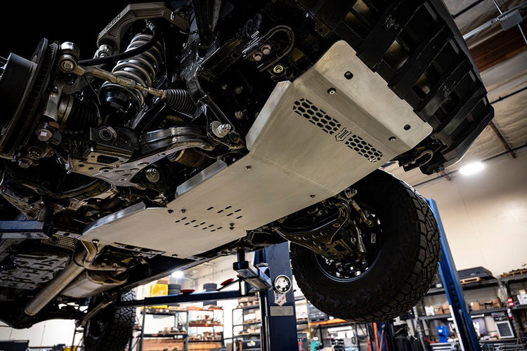
ICON's Latest Video: 6th Gen 4Runner Skid Plate System
Protect What Matters Most: ICON Skid Plates for the 2025 Toyota 4Runner ICON Vehicle Dynamics introduces our all-new Skid Plates, purpose-built to defend your 2025 Toyota 4Runner’s most critical underbody components from trail damage and debris. In this video, ICON's Scott Spiva gives you a complete walkthrough of these premium upgrades, highlighting how they integrate seamlessly with your vehicle’s factory setup for a clean, bolt-on installation with no drilling, cutting, or welding required. Whether you're crawling through rocks or navigating rugged trails, ICON skid plates are engineered to take the hit so your drivetrain doesn't have to. Check out the video below!

Tales From The Tech Line: Picking Ratios… A Jeep JK Re-Gearing Story
Customer Question: Can you advise on a recommended gear ratio for a 2017 Jeep Wrangler four-door with a 3.6-liter motor running 35 inch tires? … Would it be 4.56 or 4.88? Gus: Is it an automatic or manual transmission? How will it be used? Customer: Automatic. It’s a daily driver and weekend warrior off-roader. I do some off-road driving for my job during the week. I’m running 3.73s currently. Gus: The 3.6-liter finds its happy place cruising in the 2,000 to 2,500 rpm range, they aren’t really known for bottom-end torque. Check the graph above.
New From ICON Vehicle Dynamics: 2024 (4th Gen) Toyota Tacoma Skid Plates
NEW PRODUCT 2024 (4th Gen) Toyota Tacoma Skid Plates Protect your 4th Gen Tacoma's most vulnerable undercarriage components with the ICON Front Skid Plate and Transmission Skid Plate. Together, these components form a rugged defense for your truck's critical drivetrain components. The Front Skid Plate integrates closely with the stock front bumper (with lower valance removed) and provides protection rearward to the differential crossmembers. The Transmission Skid Plate continues this armor protection to the transmission crossmember. Both skids are CNC laser cut and precision brake-formed from a rugged but lightweight 5052 aluminum alloy plate. This is a 100% bolt-on system that requires no drilling, cutting, or welding for an easy, factory-clean installation. FRONT SKID PLATE 56116 24 TACOMA FRONT SKID PLATE KEY FEATURES: 5052 aircraft-grade aluminum 100% bolt-on system - no drilling, cutting, or welding necessary for install TECH NOTES: Ships in multiple boxes Removal of factory front valance required. TRANSMISSION SKID PLATE 56117 24 TACOMA TRANSMISSION SKID PLATE KEY FEATURES: 5052 aircraft-grade aluminum 100% bolt-on system - no drilling, cutting, or welding necessary for install TECH NOTES: Will not work on manual transmissions DOWNLOAD PRICING & SPECS
Subscribe To Our Newsletter
Sign up & unlock 5% off. Get news on insider deals, product releases, and expert advice.