randys blog

Instalación de sellos de ejes, los 10 mejores consejos
Como sucede con muchas de las operaciones automotrices, la complejidad de una tarea no siempre es representativa de su importancia. Tomemos como ejemplo la instalación del sello del eje... un asunto bastante sencillo, pero si se hace mal, el diferencial está condenado a morir. El sello del eje tendrá fugas y, en última instancia, provocará la falla de los engranajes. Para evitar este problema, hemos compilado 10 tips de instalación que asegurarán que el trabajo esta bien hecho. Existen muchos diferentes tipos de sellos de eje. Para nuestro propósito, nos referiremos al popular sello radial dinámico. Estos sellos cuentan con una carcasa de acero al carbono suave. En los casos en que la preocupación sea la corrosión, la carcasa puede ser fabricada de acero inoxidable. En la mayoría de los casos, el sello estará equipado con un resorte como una liga para mantener el labio del sello apretado hacia la superficie giratoria del sello. El resorte toroidal está hechos de alambre de acero para resortes y, en algunos casos, de acero inoxidable y se pueden fijar en un lugar o simplemente encajar en su lugar, por lo que se debe prestar especial atención para garantizar que quede asentado correctamente durante la instalación. El interior del sello se llama labio y generalmente está hecho de algún tipo de material de goma. El labio puede tener un aspecto diferente entre un sello y otro, y algunos presentan un diseño escalonado o más de un labio. El caparazón tiene un tope de sello en su lado de aceite que está hecho de un material más suave para proporcionar un sello flexible. 1 – Las herramientas correctas para el trabajo Se refiere a la herramienta para la instalación de sellos en particular con el que se va a trabajar. Los kits de instalación de sellos que se encuentran en la tienda local de repuestos o de herramientas en línea son muy económicos, duraderos y efectivos. A veces una llave de cubo te puede sacar de un apuro. La herramienta de instalación de sellos del eje interno delantero de Yukon (en la imagen) funciona con los diferenciales delanteros Dana 30, 44 y 60. 2 - Inspeccione y detecte – Eje Inspeccione el eje donde se instalará el sello. Esas pequeñas imperfecciones en el acabado se pueden pulir con tela de azafrán o tela de esmeril. Si existen defectos diferentes como rayones profundos, picaduras o estrías, es posible que el remedio sea con un eje nuevo o instalar un manguito Speedi. Si el eje no tiene imperfecciones, límpielo bien para eliminar cualquier resto de arenilla. 3 - Inspeccione y detecte – Carcasa Tome el mismo enfoque con la carcasa. Busque algunas marcas obvias habituales, pero también verifique si hay redondez. Debe haber un borde achaflanado alrededor del orificio para ayudar en la instalación del sello. Se puede agregar un ligero chaflán, si es necesario, usando una lima de dientes finos. Más allá de eso, limpie el área y el exceso de aceite. 4 - Sellar el trato En el diámetro exterior del sello o carcasa es aconsejable aplicar un sellador como un RVT, para garantizar que no se filtre líquido alrededor del sello una vez que esté instalado. Tenga en cuenta que muchos sellos están fabricados con un recubrimiento en su diámetro exterior para ayudar en esto. 5 – Instrucción de montaje Sea deliberado y asegúrese de colocar el sello directamente en su lugar. No permita que el sello entre en el orificio de manera inclinada y que posiblemente dañe el sello y/o el orificio del sello. Mantenga el sello alineado e instálelo hasta que quede al ras con la carcasa o contra su tope. Sería prudente tener muy en cuenta la posición del sello original antes de quitarlo. 6 - Cara hacia adelante Instale el sello de modo que el resorte toroidal quede hacia adentro, hacia los fluidos que desea sellar. 7 - Estabilidad del resorte En algunas instalaciones, durante este proceso el resorte toroidal puede salirse. Para evitar esto, simplemente aplique grasa en la parte posterior del sello (o vaselina en caso de necesidad) para alentar a que el resorte permanezca en su lugar. 8 - Protección del labio Al deslizar el sello sobre el eje, asegúrese de proteger el labio o el borde. Esto se puede lograr con unos manguitos especiales sobre las estrías, utilizando placas guía, o simplemente utilizando una cinta lisa… o con mucho cuidado. Una extensión atornillada al espárrago de un semieje, por ejemplo, puede proporcionar el control y el soporte necesarios para completar la instalación sin tener que descansar sobre el eje. 9 - Lubricación de labios Use grasa o aceite para engranajes para lubricar el labio del sello y/o el eje para facilitar la instalación. 10 - Espacio libre de ventilación Verifique que el respirador del eje esté libre de cualquier acumulación de arena. Esas áreas de respiración cuando están obstruidas pueden provocar una presión excesiva en la carcasa que puede acelerar el desgaste del sello y fomentar la fuga de aceite alrededor del sello. Estos consejos, recopilados del libro de Randy Lyman, "Identificación del diferencial, restauración y reparación del diferencial", brindan información técnica correcta para garantizar una instalación del sello sin problemas. Shop Yukon Axles
Tech Tidbit: All-Wheel-Drive Roll-Out Tire Test
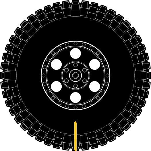
Harmony, balance, and smoothness… are all attributes of a healthy all-wheel-drive system. While there are many component systems that have to work hand in hand, tires are often taken for granted and overlooked by enthusiasts and shop owners alike. A simple roll-out test will ensure your tires are in sync with the driveline. Why A Roll-Out Tire Test? Symptoms of an un-even roll out include, the vehicle pulling to one side, strange locker operation, worn spider gears, worn LSD clutches, and stress on the differential and transfer case. Over time the stress put on transfer case internals can lead to poor performance, and ultimately, failure. Tire Size Looking at an all-wheel-drive vehicle from a four-corner standpoint, with each corner represented by a traction tire, you want to achieve a balance of circumference at each corner. When one corner is moving at a different speed, faster or slower, than the other corners due to a difference in circumference, the resulting imbalance creates stress that will be transferred to the weakest link, which is usually the internal components of the transfer case or the differential. Many customers think replacing a worn tire is a way to fix this issue. Even if it’s the same exact size, tires from different manufacturers have different circumferences… heck even same-sized tires from the same manufacturer but in a different model can have different circumferences. This means problems are still possible. There is a reason why all-wheel drive vehicles, especially Subarus, mandate replacing all the tires at once… it keeps the Symmetrical All Wheel Drive system… symmetrical, happy, and in balance. Buying four tires at a time ensures you’re purchasing from the same production batch and that the tires are well matched. Tire Pressure Tire pressure can also have an impact on the likelihood of trouble. Mis-matched pressures between tires can lead to circumference differences which can result in differences in tire rotation speeds, thus opening the door to uneven drivetrain loads. The Roll-Out Test Step 1: You will need two people, one to view and measure and one person to operate the vehicle. Mark each tire exactly in the 6 o’clock position with a paint stick or chalk. Step 2: Using the front driver’s side tire as the reference tire, have one person drive the vehicle as the other person monitors the driver’s side tire and counts out 10 revolutions. Let it slowly roll forward then stop and creep it forward until the front driver’s side tire mark is once again in the 6 o’clock position. You can mark the pavement at 6 o’clock to serve as a visual reference to better compare each tire. Step 3: Put the transmission in park/neutral. Then check the other three tires and see how the tire marks present. If any of the other marks are not at 6 o’clock, your tires are not revolving at the same speed and there may be undue load being transferred to your transfer case and/or differential. If a mark is off by more than an inch, you may have a bad tire or you’ll need to check your tire pressure… or both. Step 4: If you’ve checked tire pressure and a difference remains in your tires, see your local tire retailer for new tires. As mentioned above, it may be wise to replace all four tires simultaneously with the same/similar date code in order to ensure you’re getting tires from the same manufacturing batch. A properly conducted roll-out test can be a quick and easy way to possibly identify the root cause of a customer’s ongoing issue. You come off as a superhero, the customer is happy, and he or she will be back to support your business in the future. A win-win for sure.

RANDYS At SEMA 2021
As the industry spools back up to fever pitch we are happy to back at the SEMA Show in force. We’ve spent the week in Sin City reconnecting with customers, inviting new friends to ‘Run With The Bear,’ and promoting the off-road lifestyle any way we can. Click the link below to experience the SEMA Show yourself through interviews with industry insiders conducted by TV personality Ian Johnson. View Our SEMA Coverage
4 Reasons The Ford 9-Inch Is The Ultimate Performance Differential
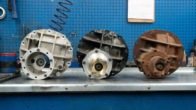
The iconic Ford 9-inch has been the go-to diff for hot-rodders since day one. The brilliance of the unit is its ability to hold power, its quickness in changing gears, its vast range of available gear ratios, and the ease in which it can be setup. Shop our Ford 9-inch differential products here. The Ford 9-inch was produced from 1957 to 1986 and came standard in a wide variety of Blue Oval cars and trucks. As one would expect, the aftermarket has kept the 9-inch alive, offering its own versions of the long-standing design. Spotting A Ford 9-Inch The Ford 9-inch is a dropout-style differential. Looking at the pumpkin, or center section, you’ll notice the gear set is accessed through the center cover on the pinion side of the axle where the driveshaft connects, not from the back over like a more common carrier-type of rear end. Early, pre-1966 9-inchers have a round housing where later versions of the 9-inch had a hump integrated into the housing. All 9-inches are not created equal. Ford produced diffs with many different widths ranging from 57 ¼” to 69 ¼” measured from the outer flanges on each axle tube. While on the topic of spotting Ford 9-inchers, it’s worth mentioning there is a Ford 9 3/8” diff. None of the parts interchange with the 9-inch. This pretender can be identified externally by the top horizontal rib curving down at the end… which is kind of frowning, like people do when they realize it’s not a ‘real’ 9-inch. Holding The Power “In real world applications OE third members were produced in many different configurations and materials,” says Gus Pyeatt, RANDYS Worldwide tech support specialist. “The majority were just a common grey iron with minimal ribbing, these start to see fairly significant deflection in a light car around the 300-horsepower mark, less in heavy cars and trucks. There were some factory HD or “N” nodular iron cases that had much more pronounced webbing. These will usually hold about 400 horses in a street car application before seeing significant deflection. Aftermarket cases enjoy a huge jump in rigidity even when reducing weight by going to aluminum. The power handling in these custom cases more than triples to the 1,200 range. Add in big bearing cases with 10-bolt pinion supports and thru-bolted caps, and you see many 9-inchers that hardly notice 2,000 horses being thrown at them.” Other Ford 9-Inch Performance Advantages Beyond corralling horses, the Ford 9-inch’s performance advantage includes its ease of serviceability, and for early hot-rodders, its versatility. These founding father enthusiasts had the ability to drive to the track with highway gears, then swap in another third member with deep gears and a spool, race or do their shenanigans, then swap back at the end of the day. According to Gus hot-rodders also liked how lightweight the stamped steel “banjo” housing was and its ease in adapting to other applications. “Sheetmetal is much easier to weld on and otherwise alter than cast iron. As time went on, ratio selection exploded, allowing the circle track racers to fine tune gearing from track to track all but making the old “quick change” rears obsolete.” The 9-inch’s design benefits performance from a ‘bigger is better’ standpoint as well. Ford 9-inch diffs feature larger diameter ring gears which creates additional distance between the centerline of the ring gear and the centerline of the pinion gear, known as hypoid distance. This relationship impacts performance. “The key here is hypoid offset,” says Gus, “The vertical offset from the axle centerline. It’s not something that is adjustable, it’s engineered into the gear set and housing. It’s a balancing act, the more the offset, the larger your tooth contact on the gears, which has the effect of strengthening the rear end assembly. The offset also changes how the pinion shaft is loaded, with 0 offset the pinion shaft sees the load at a 90-degree angle, as the offset is increased the angle is reduced, and becomes more in line with the pinion shaft, which allows for a shorter pinion shaft to handle the leverage.” The Ford 9-inch pinion gear features a stub on the gear end. The stub is supported within the housing (red arrow) via a pilot bearing. “Ford went so far as to further improve that side load issue by adding a third bearing which splits the load between the two bearings rather than using the single bearing as a fulcrum. The gear end of the pinion features a stub that provides additional support to the pinion via that third bearing, along with splitting the load this setup also benefits performance by limiting gear deflection under high-torque loads.” Shop our Ford 9-inch ring and pinion gear sets here. It should be noted that there is a slight drop in efficiency with hypoid offset but it’s nominal. Nevertheless, there are some on the interwebs that characterize this inefficiency as blasphemy and liken the 9-inch to a boat anchor. “We are talking 1% to 2% difference,” says Gus. “For some users that change will be a minimal concern, for a competitive team it may be a deal breaker. But it is enough of a concern that good old corporate average fuel economy helped force the 9-inch out of production.” The Ultimate Gear Swapper The Ford 9-inch’s removeable front gear case makes swapping gears incredibly easy. Simply unbolt the gear case, lift it out, and move it to the workbench. This way all the assembly and setup can be done more comfortably on the workbench rather than under the vehicle as in most carrier-type diffs. When it comes to gear ratios, the sky is the limit. There are more available gear ratios for the Ford 9-inch than most any other differential. Offerings ranging from the low 3s to mid 6s, in increments that measure down to tenths of a ratio make it easy for the Ford 9-inch owner to swap gears and tune their traction with unrivaled precision. Troublesome Troubleshooting It’s not all roses and unicorns with the Ford 9-inch. Troubleshooting can be difficult in a Ford 9-inch because you have to commit to removing the entire carrier where in a typical GM 10- or 12-bolt carrier diff you can simply pop the cover off and glean the inner workings for any worn or broken parts. The caveat here is some aftermarket 9-inch diffs are outfitted with rear ‘inspection’ covers for just this scenario. Easy Gear Pattern Adjustments In a Ford 9-inch the pinion gear and accompanying small parts are installed in their own separate, detachable sub-housing, often referred to as a cartridge or pinion support. This arrangement promotes easy adjustments to gear set alignment. Here we see the retaining bolt being loosened to remove the adjuster lock, a Yukon side adjuster tool, and the adjuster being manipulated. Further, the 9-inch has screw-type adjusters rather than shims, which makes dialing in the gear set all the more easier because you don’t have to worry about preloading the shims to evaluate gear tooth alignment. Simply tighten or loosen the adjuster nuts on both sides of the housing to move the gear until proper alignment is achieved…. No shim hammering, no headaches. Time Is On Your Side Although Ford ceased production in ‘86, the aftermarket has not missed a beat, developing parts for the diff that take full advantage of all the advancements in technology, materials, and manufacturing through the ensuing decades. Some of these revelations include aftermarket cases made from tough nodular iron and billet aluminum not the gray iron used in the originals. The aftermarket Ford 9-inch differential at left consists of a Yukon nodular iron case, Yukon aluminum pinion support, and a Yukon yoke. The aluminum pinion support allows the use of a larger-than-stock bearing, further enhancing the unit’s durability. Beyond the diff, the evolution of axle technology will also impact the strength and longevity of the diff. The use of chromoly and other materials and the development of custom axles with more splines than stock offerings all make for a more robust differential. Even the ring and pinion gears themselves have not escaped as larger gear sets are being made from exotic high alloy steels. Enthusiast drivers are the big winners. They get a diff that can hold more power and live longer than the originals could ever dream of. The possibilities are endless and we appreciate all the Ford 9-inch brings to the table. In fact, RANDYS Worldwide and its Yukon Gear & Axle brand offer tons of Ford 9-inch parts so you can properly build and gear your diff to match your power levels and driving habits. Ready to step up to the big time? Let us help. Shop Ford 9-Inch Gear Sets
12 Tech Tips For Differential Assembly & Setup
This quick primer of tech tips is designed to be informational for less experienced installers and a refresher course for seasoned differential technicians. The focus is on time-saving tricks and advice when assembling and setting up a differential, concentrating on preparation, assembly, setting pinion depth, backlash, and more. Anatomy Of A Gear Tooth In order to take full advanatge of the tips and information conveyed in this article we need to get our lingo on the same page. The above schematic outlines the surfaces of a typical gear tooth and how they are generally referred to. 1. Take The Right Approach The order in which adjustments are made during differential assembly and setup are: 1. Pinion Depth 2. Pinion Bearing Preload 3. Backlash 4. Carrier Bearing Preload 2. Pattern Adjustment Cause & Effect Use shims to move the ring gear closer to the pinion to decrease backlash. Use shims to move the ring gear farther from the pinion gear to increase backlash. Use shims to move the pinion closer to the ring gear to move the drive the pattern deeper on the tooth (flank contact) and slightly toward the toe. The coast pattern will move deeper on the tooth and slightly toward the heel. Use shims to move the pinion farther away from the ring gear to move the drive pattern toward the top of the tooth (face) and slightly toward the heel. The coast pattern will move toward the top of the tooth and slightly toward the toe. 3. Remember Your Shim Combination When it comes to shim selection use the same shim combinations from the previous assembly as a baseline when reassembling the differential. 4. Seal Surface Preparation It is wise to polish all seal surfaces with fine-grit emery cloth or sandpaper then wipe all surfaces with a clean rag dampened with either fresh oil or solvent to remove any metal particles. 5. The Importance Of Using Assembly Oil When assembling internal components, coat all bearings and seal surfaces with fresh gear oil. Never use bearing grease on pinion or carrier bearings because it will negatively influence assembly measurements. Coat all seals with grease, preferably white lithium grease. Use clean gear oil if white grease is not available. 6. Trial Pinion Assembly Mock install the pinion with its original shims yet without a crush sleeve to establish an approximate pinion depth. When installing the pinion, tighten the nut slowly until it reaches preload specifications. 7. Initial Carrier Assembly Install the assembled gear carrier with its ring gear into the housing. It is easier to remove and replace the carrier during trial assemblies if the carrier bearing preload is fairly snug instead of tight. 8. Initial Backlash Adjusting Tip Backlash refers to the amount the ring gear can rotate forward and backward when the pinion gear cannot move. The initial backlash setting establishes the basis for all future adjustments. To start, fasten a dial indicator to the gear case or axle housing on the same plane as the ring gear so its contact point touches a tooth at the outermost diameter of the ring gear in a 90-degree relationship to the tooth face. The indicator should measure the amount the ring gear moves when rotated. To measure backlash, prevent the pinion gear from rotating and rotate the ring gear back and forth. The amount the ring gear can move (the amount of play) determines the amount of backlash. When changing the backlash bear in mind that the backlash setting changes about 0.007” for each 0.010” that the carrier moves. For example: Move the carrier 0.010” toward the pinion to decrease the backlash by 0.007”. Move the carrier 0.010” away from the pinion to increase the backlash by 0.007”. This gear pattern indicates the pinion is too close to the ring gear centerline. Use shims to position pinion away from centerline. This gear pattern depicts a pinion that is too far way from the ring gear centerline. Use shims to position pinion closer to the centerline. This is the proper or desirable pattern. Note how the pattern is centered on the tooth from face to flank. There should be some clearance between the pattern and the top of the tooth (face) and between the pattern and the bottom of the tooth (flank). Learn more about ring gear patterns in our “How The Create & Read Ring Gear Patterns” article. 9. Make Large Pinion Depth Adjustments First When changing pinion depth, make large changes until the pattern is close to ideal. Consider 0.005” to 0.015” a large change and 0.002” to 0.004” a small change. Intentionally, make adjustments that move the pinion too far at first. If the pinion moves too far and the pattern changes from one extreme to the other, the correct pattern lies somewhere between the two extremes. Once you home in on the correct pinion depth, make smaller changes until the pattern centers between the face and the flank of the ring gear teeth. Once the backlash and pinion depth meet tolerances, remove the carrier and establish the final pinion bearing preload. 10. How To Fine Tune Backlash If the preload is close and the backlash is too loose, tighten the left adjuster a notch or two until the backlash is correct and the preload is sufficient. If the preload is close and the backlash is too tight, tighten the right adjuster until the backlash is correct and the preload is sufficient. Note: ensure that the last adjustment made to the left adjuster tightens it. Doing so will eliminate the possibility of a space between the adjuster and the bearing race. 11. Shimming Outside Shim Design Carriers This design uses shims between the carrier bearing races and the housing. Initially, set the backlash with very little carrier bearing preload. After setting the backlash, add equal amounts of shims to both sides of the carrier to set the carrier bearing preload as tight as possible without damaging the shims (carrier bearings in this axle design hardly ever fail due to excessive carrier bearing preload). If the preload is close and the backlash is loose, add shims to the left side. This increases the carrier bearing preload and tightens the backlash at the same time. If the preload is close and the backlash is too tight, add shims to the right side. This increases both the carrier bearing preload and the backlash at the same time. 12. Shimming Inside Shim Design Carriers This design uses shims between the carrier bearing and the case. Initially set the backlash tight and the preload light, as it will make carrier removal and installation easier. After setting the backlash, add equal amounts of shims to both sides until the correct preload is achieved. If the preload is close and the backlash is loose, add shims to the left side. This increases the carrier bearing preload and tightens the backlash at the same time. If the preload is close and the backlash is too tight, add shims to the right side. This increases the carrier bearing preload and the backlash at the same time. Shop Re-Gear Kits
Subscribe To Our Newsletter
Sign up & unlock 5% off. Get news on insider deals, product releases, and expert advice.