randys blog

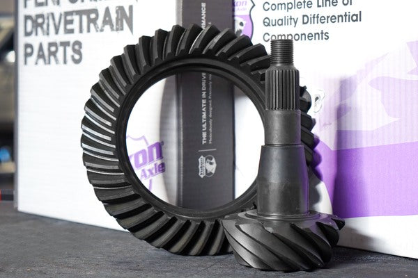
Tales From The Tech Line: Keeping Gears Cool During Break-in
August 11, 2021 - 10:18 AM - Tech Question: I just installed your Yukon limited slip carrier and 3.42 ring and pinion in my GM 10 bolt. I’ve been breaking it in correctly. It’s been about 120 miles so far and it’s still hot to the touch. I can keep my hand on it for about a second or two. When will this thing start running cooler and when would you recommend my first oil change? Thanks. Tech Visitor, RANDYS Worldwide Website Tech Answer: Hot to touch is a poor form of measurement… most people struggle to hold a cup of coffee that is 140°, a shower at 120° will scald you. The normal operating temp of a differential is 175° to 250° depending on the type of driving you’re doing. We recommend using a handheld infrared digital thermometer which cost $15 to $50 to get a more accurate temperature reading. Use your findings in the chart below to determine your oil change interval. Temp Reference / Oil Change Frequency Chart Temperature Frequency 170° 100,000 Miles 200° 50,000 Miles 220° 25,000 Miles 240° 12,000 Miles 260° 5,000 Miles 260°-300° 500-1,000 Miles until temp is controlled Running 250° to 275° is normal for new differentials during the break-in period. It is critical to not tow or take long road trips for first 500 miles as this builds additional heat. At 300° the diff is considered too hot and it should be allowed to cool. Once broken in, the normal operating temperature for a differential for vehicle in stock trim and regular diving is 170° to 220°. Normal operating temperature on vehicles with large tires, undersized differentials, or while towing is 200° to 250°. Remember, a new gear break-in requires an oil change at 500 miles. Gus Pyeatt, RANDYS Worldwide Tech Support For more info on gear oil and additives check out this article. For more info on gear set break-in procedure check out this video.

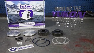
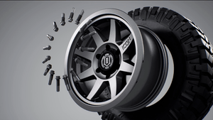
Unboxing: Hardcore Drive Flange
Designed for serious off road use, the Yukon Hardcore Drive Flange Kit features a drive flange made from high strength heat treated 9310 steel. We'll show you all the parts that come in this kit that's available for Dana 60, Dana 44, and GM 8.5" differentials.

Tech Tips: Measure a Semi-Float Rear Axle Shaft
A demonstration on how to properly measure a semi-float rear axle shaft. How to identify ring & pinion gear ratio.
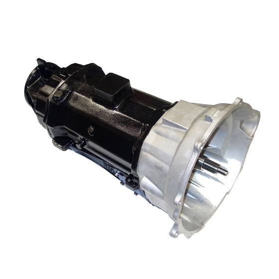
Troubleshooting The NV5600 Transmission
The New Venture Gear 5600 series six-speed manual transmission is a great gearbox with a lot on its plate, namely the 5.9-liter Cummins inline six-cylinder turbo diesel. With all that torque to deal with there were a few teething problems in its early years. Some NV5600 units, produced from 1998 midway thru 2000, are known to have synchronizer problems and a weak input shaft. In response to many issues owners had regarding these components, especially while towing heavy loads, the NV5600 received an upgraded clutch, input shaft, and improved synchro design for model year 2001. The 5 Most Common NV5600 Manual Transmission Problems 1) Noise when accelerating, noise when decelerating. Issues associated within this symptom are generally associated with input bearing or pocket bearing malfunction, sixth gear failing, or the pilot bearing could also be compromised. 2) Difficult to shift into gear. This problem is common. The NV5600 is more like a large 18-wheeler transmission, double clutching at the right RPM is key to resolving this problem. Additionally, there may be a clutch hydraulics issue that may require replacing these components. 3) Grinding when shifting gears. This issue can be excessive wear of the synchro rings as well as excessive bearing wear. The rings will need to be replaced. 4) Jumping out of gear. This problem may be related to worn synchro rings, synchro sliders, gears and/or shaft movements caused by extreme bearing wear. Again these small parts will need to be replaced or a remanufactured transmission installed. 5) Will not shift from gear to gear. Fluid varnish build-up around the shift rail bushing exacerbates this problem. The fix is regular scheduled gearbox maintenance. NV5600 Transmission Specifications Manufacturer: New Venture Gear Production Years: 1998 – 2005 Applications: 1999 – 2005 Dodge Ram 2500/3500 Input Torque Rating: 550 lb-ft or 650 lb-ft (Heavy Duty, NOT used in Dodge Ram trucks) Weight: 360 lbs Oil Capacity: 9.5 pints (10 pints w/ optional filter) Construction: Cast Iron Case, Aluminum Bellhousing Improved Version: Introduced in 2001 with upgraded synchros, clutch, & input shaft NV5600 Transmission Gear Ratios 1st 5.63 2nd 3.38 3rd 2.04 4th 1.39 5th 1.00 6th 0.73 Reverse 5:63 Shop Re-Man NV5600 Transmissions
Subscribe To Our Newsletter
Sign up & unlock 5% off. Get news on insider deals, product releases, and expert advice.