randys blog

Differential Install: Small Details Make a Big Difference (Part 1)
Taking care of the details requires knowing which details are important, and having the discipline to check every detail on every job. Here is a partial list of details that we have found to make a difference when assembling a differential. Pay very close attention to the bearing hubs on the carrier case. If the old carrier bearing spins on the case, the new bearing will not fit tight and will also spin. Any wear due to a spinning carrier bearing will cause the backlash to open up and the ring & pinion gears will eventually break. Look carefully at the side gear bores and thrust washer surfaces to make certain they are not worn or galled. Make sure the cross pin shaft bores fit the cross pin tightly. Check the ring gear flange with a dial indicator to make sure there is minimal or no run-out. There are a lot of opinions as to how much carrier run-out is acceptable. We have seen as little as 0.005″ cause problems and we have seen differentials work fine with 0.009″ or more. The main thing that we look at is backlash variation. Keep the backlash variation under 0.005″ if possible. In a perfect world no variation would be the goal. However, even with a straight case the backlash can vary 0.005″ without any negative consequences, so this is an area where each assembler will have to decide how much they are willing to allow. Also look closely at the spider gears and cross pin shaft. The spider pinion gear and side gear teeth should be without pits or chips, and should not show any signs of heavy wear at the base of the contact patch. The spider pinion gears should not have any heavy wear or galling on the inside where they contact the cross shaft, and the cross pin shaft should show no more than light; even wear on the surface that contacts spider pinion gear without scratches or galling. The pinion yoke is another part that can cause a lot of problems if it is not in good shape. It is good idea to inspect the ears or shoulders that retain the universal joint. If there is any wear in these areas it is best to replace the yoke. Also inspect the seal surface closely. Small grooves or light rust can sometimes be polished away, but any irregular spots can cause the seal to leak if they do not polish out completely. Repair “redi sleeves” are available to press on the yoke and replace the seal surface of my popular models. These sleeves work fair in most cases but usually do not hold up as long as a new yoke The most often overlooked problem that we have found with yokes is the splines. On some models the splines seem to last forever, and on some they loosen up quickly. The splines should always fit tight and it should take a lot of pressure or pounding to drive the yoke down until it seats against the outer pinion bearing. One other area to inspect on the yoke is the surface that touches the outer pinion bearing or slinger. If this surface has light wear it can be filed down flat with a hand file as long as the surface is kept true and is not filed unevenly. Popular Resources: Limited Slips: Gov-Lock vs. Yukon Dura Grip Identifying Borg Warner Transfer Cases Limited Slips vs. Differential Lockers vs. Spools
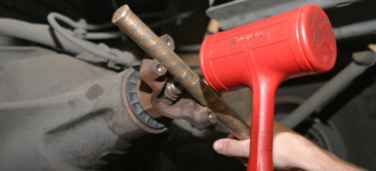
Tight Yoke Installation
In many cases when installing new yokes on Ford 10.25”and 10.5” as well as some other differentials, it can be difficult to get the yoke over the pinion splines. The fact is, many pinion splines have a slight “twist” to them (which controls rotational “slop”), but the Ford 10.25” & 10.5” pinion splines have a slightly tighter fit than most. As a result, they make it difficult to get a new yoke over the pinion splines, and it’s an even bigger challenge when installing a new yoke over a new pinion gear. The solution? There really isn’t one, you’ve just got to use good old-fashioned force. Generally, it’s a two person job. One technician holds the pinion in the backside of the housing, while the other cradles a brass punch in the yoke and use a dead blow mallet to drive the yoke into place (See Pic). Keep striking the yoke until the pinion nut threads are exposed enough to get a few turns of the pinion nut on the pinion, then use an impact gun to get the yoke seated. (Be careful to make sure to have enough pinion thread showing to ensure you won’t strip the threads off the pinion.) It sounds rough, we know…but it’s the only way to get the job done. Popular Resources: New Gear Break-In Properly Setting Preload with Side Adjusters Size Matters
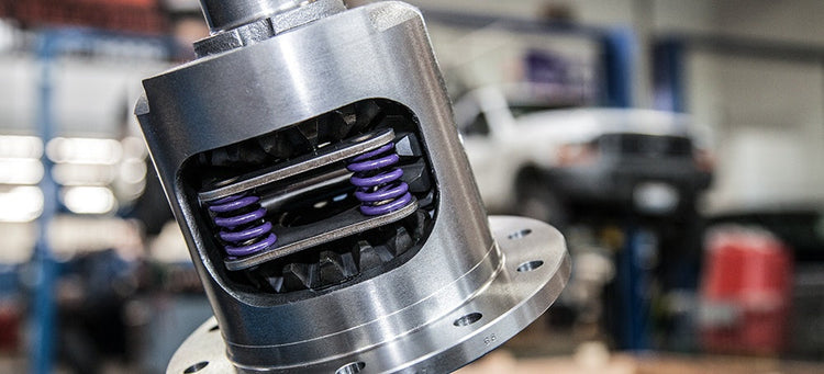
Limited Slips: Gov-Lock Vs. Yukon Dura Grip
In the early 1970s, real muscle cars were fading away, and average Americans were becoming more concerned with a plush ride than with high performance. In the 1973 model year, General Motors decided to start using the Gov-Lock in trucks, in an effort to eliminate chatter associated with conventional spring preload clutch type positractions limited slip differentials. This was the one of the few solutions available using 1970’s technology. Thus, for GM trucks produced after 1972, the only traction-enhancing option was the Gov-Lock (produced by Eaton). These governor actuated units provide a locking differential without chatter. Great for the average truck owner, but not for those who really use their trucks off-road. Often referred to as a “time bomb” or “Timex Posi”. These locking differentials work fairly well for occasional use when traction is of small concern, but not when power transfer and traction are the main goal. The Gov-Lock can fail in any number of ways, and often does. Usually, the case will break in half, but sometimes small internal parts will break. I have no intention of defending them except to say that the Gov-Locks used in 3/4 & 1 ton trucks hold up fairly well due to their sheer size, and especially well when compared to the smaller designs. For readers looking for something stronger, Yukon makes redesigned units that are worth showing off. The Yukon Dura Grip is not actually a “new” design so much as a vast improvement on the old design. The basis for these new units is the heavy-duty positraction that was originally produced for big block GM muscle cars in the 60s and early 70s. Dura Grips now come with composite clutches that are more durable than their steel counterparts. New units also use stronger spider gears produced with Net Form Forging technology. These stronger spider gears look very different compared to standard cut gears. They are made from 8620 steel to increase strength and durability. Net Form Forged gears perform at least 20% better than standard cut gears in both impact testing, and testing for fatigue under heavy loading. In addition to the other improvements, Yukon has improved the case designs. The original 12-bolt truck positraction was very similar to the passenger car design but was not nearly as strong as it’s passenger car counterpart. The new 12-bolt truck cases are about three times stronger than the original ones used in the early 1970s, and all Yukon Dura Grip cases are now made of nodular cast iron with increased material thickness in critical areas. The new 10-bolt cases now have larger bearing journals that increase the case strength and use bearings with more rollers than stock. Overall, the new Dura Grips are superior to the admired and sought after original OEM GM positraction. By using 90’s technology, Yukon has built a stronger, harder working positraction that does not chatter. Yukon has developed Dura Grip limited slip differentials for: Chrysler 9.25″ Dana 44 Dana 50 Ford 7.5″ Ford 8.8″ Ford 9.75″ Ford 10.25/10.5″ GM 7.5″ GM 7.625″ GM 8.2″ GM 8.5/8.6″ GM 9.5″ GM 11.5″ GM 12 Bolt Passenger Car GM 12 Bolt Truck GM 10.5″ 14 Bolt Truck Nissan Titan CI Corvette 17 Spline Popular Resources: Ford 9 Inch Differential Information Four Critical Ring & Pinion Settings
How To Create & Read Ring Gear Patterns
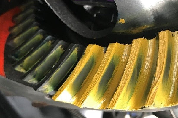
Gear tooth patterns are harbingers… they can foretell whether your ring and pinion gear set is going to live a long and prosperous life or if it’s doomed to an impending catastrophic failure. Pulling off a proper differential setup comes down to precise adjustments. Parameters like pinion depth, backlash, pinion-bearing preload, and carrier-bearing preload allow you to fine tune the relationship between gear teeth to ensure proper meshing and ultimate durability. Checking the Pattern We can determine how gears mesh by changing how close the pinion gear is to the ring gear centerline. While we can’t physically see how the gears actually relate to each other, we can coat their mating surfaces with gear-marking compound and read the patterns the gears create as they mesh. Genuine gear-marking compound offers a clear indication of gear contact without running or smearing. Anything other than gear marking compound (such as blue machinist dye) will not give a clear indication of tooth contact. Dilute the marking compound with a small amount of oil if necessary to create a smooth, but not runny, paste. Coat three or four ring-gear teeth in at least two places with a moderate amount of compound and rotate the ring gear around the pinion gear four or five times in both directions. Rotate by grabbing and turning the ring gear, not the pinion. Pinion resistance against the rotating ring gear helps establish a good pattern. Pinion bearing preload usually provides enough resistance for a good pattern, but additional resistance can be added by wrapping a shop towel around the yoke and pulling the two ends tight. An alternative method for checking gear patterns in cases where reading the pattern is difficult involves spinning the pinion. Paint three or four ring gear teeth as usual on both coast and drive sides of the teeth. Using a ½” drive adapter on a hand drill (not on an impact gun/driver) spin the pinion for 30 to 60 seconds in each direction while applying drag to the edge of the ring gear. Not only does this typically produce a clear, well defined pattern on the painted teeth, but it creates a negative or “ghost” pattern on the non-painted teeth that may provide additional insight to the pattern, while also conveniently showing any potential run out issues (where the pattern is shifting from heel to toe as the gear is rotated). This technique also helps to minimize diagonal striping in the pattern that occurs when rocking the gears back and forth, which can lead to misdiagnosed patterns. The down side of this method is more cleanup between adjustments to remove the compound but the additional data is well worth the effort. Here is a good example of the alternate technique. You can see on the bottom couple of teeth that were painted how the compound got smeared resulting in diagonal striping, and hard to read, as opposed to the “ghost” or negative patterns on the non-painted teeth being quite clear and well defined. Anatomy Of A Gear Tooth The pattern’s position to the tooth face (ridge/top land) and flank (valley/root) indicates pinion depth. Disregard the pattern’s position to the tooth’s heel (ring gear outside diameter) or toe (ring gear inside diameter). Gear patterns change from heel to toe, but in most cases an ideal heel-to-toe pattern is impossible to achieve. Furthermore, the housing itself influences the heel-to-toe pattern and the pattern cannot be changed without machine work. Trying to obtain a pattern centered exactly between the heel and toe usually leads to frustration and a noisy gear set if the face to flank pattern is not correct. Instead, concentrate only on the position of the pattern and how it relates from face to flank of the ring gear teeth. Cause, Effect, Action A contact pattern centered from face to flank indicates the correct pinion depth. A contact pattern closer to the gear face means the pinion is too far away from the ring gear. To correct the pattern, move the pinion toward the ring gear centerline. A contact pattern closer to the gear flank means the pinion is too close to the ring gear. To correct the pattern, move the pinion away from the ring gear centerline. How To Maneuver Your Pinion Pattern 1. Use shims to move the ring gear closer to the pinion gear to decrease backlash. 2. Use shims to move the ring gear farther from the pinion gear to increase backlash. 3. Use shims to move the pinion closer to the ring gear to move the drive pattern deeper on the tooth (flank contact) and slightly toward the toe. The coast pattern will move deeper on the tooth and slightly toward the heel. 4. Use shims to move the pinion further away from the ring gear to move the drive pattern toward the top of the tooth (face) and slightly toward the heel. The coast pattern will move toward the top of the tooth and slightly toward the toe. Make Large Pinion Depth Adjustments First When changing the pinion depth, make large changes until the pattern is close to ideal. Consider 0.005” to 0.015” a large change and 0.002” to 0.004” a small change. Intentionally, make adjustments that move the pinion too far at first. If the pinion moves too far and the pattern changes from one extreme to the other, the correct pattern lies somewhere between the two adjustments. Once you get close to the correct pinion depth, make smaller changes until the pattern centers between the face and the flank of the ring gear teeth. Once the backlash and pinion depth meet tolerances, remove the carrier and establish the final pinion bearing preload. Properly setting your ring and pinion gear is an important part of the drivetrain experience. Getting it right is the difference between decades of easy miles and a flurry of headaches and chunked-out gears after only a few miles. Shop Re-Gear Kits
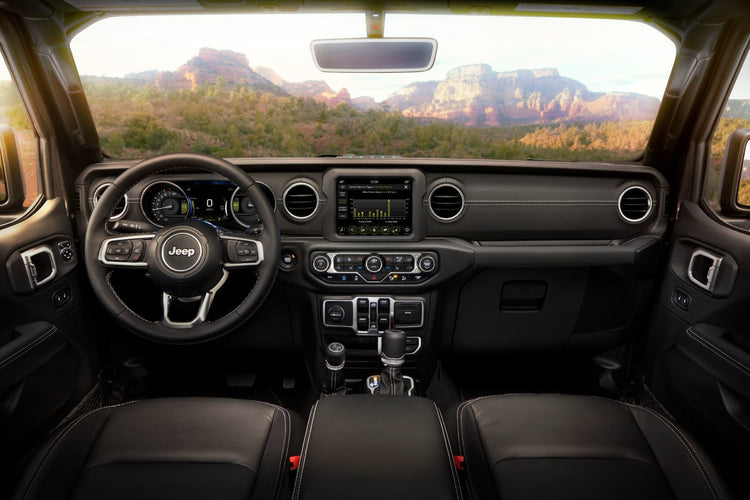
Gorilla Glass Windshields For Select Jeeps
Wrangler’s get beat on. We know this all too well as most of our products help zealous owners push the limits of their rigs to the extreme. Yukon Gear & Axle fortifies drivelines with chromoly axles, lockers and limited slips, and protects them with Hardcore Diff Covers. Jeep® Performance Parts (JPP) by Mopar has a fine line of protection parts including off-road bumpers, side steps/nerf bars, and winch kits. We were particularly impressed with Mopar’s line of Gorilla Glass replacement windshield offerings. The super strong windshield line was recently expanded to include the latest Jeep Wrangler and Jeep Gladiator models. From Jeep’s press release: “The new JPP windshield made with Corning Gorilla Glass uses the same chemical-strengthening technology as cell phone screens. Mopar’s combination of an ultra-thin Gorilla Glass inner ply with a 52% thicker outer ply makes this windshield lightweight and durable, offering superior resistance to chips, cracks and fractures from stones and off-road debris that hardcore Jeep Wrangler and Gladiator owners are likely to encounter.” Mopar/Gorilla Glass Jeep Availability 2018 – 2021 Wrangler (JL) 2018 – 2021 Gladiator (JT) 2007 – 2018 Wrangler (JK)
Subscribe To Our Newsletter
Sign up & unlock 5% off. Get news on insider deals, product releases, and expert advice.