randys blog

How It Works: U-Joints
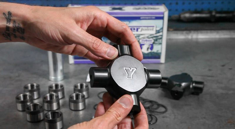
The u-joint plays a critical role in the drivetrain. They are one of those parts that are simple in their task and therefore often taken for granted. Whether in the front axle or on a driveshaft, the u-joint’s capabilities need to be understood. Doing The Job U-joints or universal joints join spinning components together while allowing them to move up and down in coordination with the vehicle’s suspension. The cross-shaped units join driveshafts to transmissions/transfer cases, differentials, and other sections of driveshafts. They also connect two-piece front axles. Types Of U-Joints There are two types of u-joints; sealed greaseable and non-greaseable. There is a long-standing debate over which style of u-joint is stronger. But independent lab testing done by various entities have proven neither style has a clear, real world advantage. You will see a four-digit number accompanying many u-joint descriptions. The numbers, 1310, 1350, 1410, 1550, and others, refer to the series, or size, of the u-joint which is determined by its dimensions. Lubrication Importance Putting all the specs aside, lubrication shortcomings are the most common cause of u-joint failure. Not keeping up with general maintenance in a greaseable unit or contamination of the lubricant in a sealed, non-greaseable joint. Other culprits include plain old wear and improper installation or poor build quality, i.e. the use of poor-quality grease or using too little grease, in a non-greaseable u-joint. Torque Multiplication When talking about strength and durability of front axle u-joints one must remember there is a torque multiplication factor at work here. It comes into play when the front driveline experiences angles and at a maximum angle of 40 degrees 30% more torque can be projected onto the u-joint. The multiplication is nominal up to 15 degrees and then the curve progresses from there. This means that a u-joint that is working near its yield point can deform if you’re crawling or bogging and putting a max load on the driveline via angularity. The workaround is to keep your wheels as straight as possible during these high load situations. Ring Clips FTW If a u-joint is being pushed to failure there are ways to increase its survivability envelope or at the very least prolong its life momentarily. It’s all about rings and clips. Using full circle snap rings in place of the traditional c-clips will resist distortion of the joint as the yoke ears begin to thrust the caps out of place. The c-clips usually used to secure the caps cannot resist the side forces very well but the full circle clips will do a better job and therefore help delay u-joint failure. The full circle clips must be installed at assembly and OE axles may require some clearancing in the yoke to allow fitment. Many aftermarket axles have grooving large enough to accommodate full circle clips. Weak Links There are two primary failure points in conventional OE-spec u-joints – the cross and the caps. The failure scenario plays out at the caps. Typically, in OE-style axles the yokes will be stressed to distortion and as they spread outward the caps are also affected. The caps move and eventually destroy the needle bearings and often become dislodged from the yoke and fall off. If the caps somehow survive the cross itself can suffer the effects of the stress by distorting and failing. Yukon Super Joints Yukon Super Joints offer an upgrade in strength and durability over factory u-joints and excel in off-road applications. Designed for Dana 60, Dana 44, Dana 30, and GM 8.5” differentials, Yukon Super Joints feature a 4340 chromoly cross and the caps are made from 4140 steel. The caps are formed from slightly softer steel to isolate the wear to the caps not the cross because it’s a lot more convenient and less expensive to replace the caps. A diamond-like coating offers outstanding wear resistance on the trunnions and corrosive resistance for the entire cross. The end of each trunnion is home to a reservoir for the grease. You’ll notice the trunnion is larger in circumference compared to conventional u-joints. This is the result of eliminating the needle bearings entirely, replacing them with a bushing setup. These joints were never designed for daily drivers. They require fanatical maintenance, greasing each of the eight caps after each long trail run. We do not recommend installing them in a vehicle that does not have locking hubs… this is NOT one of those products you can ‘get by’ with on the street. If they lose their lubrication properties the joints can gall and lock up the vehicle’s steering. They are intended for competition vehicles or dedicated off-roaders that strictly run the trails. Along with the Super Joint(s) and caps you’ll receive an installation manual, sticker, grease gun, high-quality anti-seize grease, and associated small parts like O-rings, zerk fittings, and a set of full-circle snap ring clips. Yokes and u-joints are critical links in the drivetrain’s chain of performance. Ensuring your yokes and u-joints are strong enough and properly maintained will keep you and your ride running smoothly for years to come. Shop U-Joints
Jeep Wrangler Transmission Spotter’s Guide
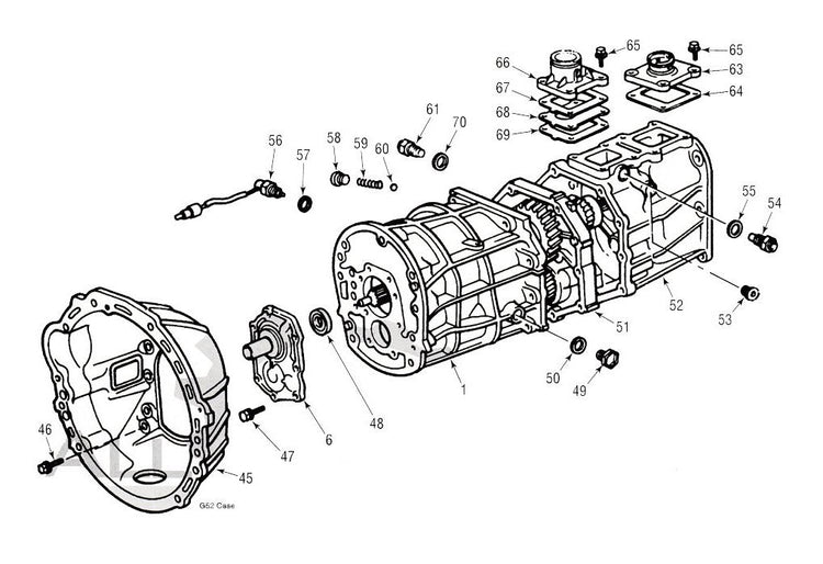
AX-15 – 5-Speed Manual Jeep Wrangler: 1988.5 - 1999 with 4.0-liter Inline 6 Factoids: Replaced weak Peugeot BA10 gearbox Related to Toyota Supra Turbo R154 manual Best 5-speed ever installed in a Wrangler Spotting Tips: All-aluminum case & mid-plate, generous ribbing Only mounts to a six-cylinder engine 10 spline input shaft 23 spline output shaft Length: 16 1/2” Spline Stick-out: 7 1/8” Gear Ratios: 1st 3.83, 2nd 2.33, 3rd 1.44, 4th 1.00, 5th 0.79 AX-5 – 5-Speed Manual Jeep Wrangler: 1984 - 2006 XJ, YJ, TJ with 2.5-liter Inline 4 Factoids: Failure prone 5th gear, poor synchronizers, throwout bearing leaks (pre ’94) AX-5 variants include Toyota G52, W58, and R151 Spotting Tips: All-aluminum case, cast iron mid-plate Looks like AX-15 so be wary Only mounts to a four-cylinder engine 14 spline input shaft 21 spline output shaft Length: 15 5/8” Spline Stick-out: 7 1/2” Gear Ratios: 1st 3.92, 2nd 2.33, 3rd 1.44, 4th 1.00, 5th 0.85 NV3550 – 5-Speed Manual Jeep Wrangler: 2000 - 2004 Wrangler with 4.0-liter Inline 6 Factoids: Replaced AX-15 Compatible with 23 spline version of NP231 transfer case Spotting Tips: All-aluminum case 10 spline input shaft 23 spline output shaft Length: 16 3/4” Gear Ratios: 1st 4.01, 2nd 2.32, 3rd 1.40, 4th 1.00, 5th 0.78 NSG370 – 6-Speed Manual Jeep Wrangler: 2005-up Wrangler, 2004-up Wrangler Rubicon Factoids: Replaced NV3550 Compatible with 4.0-liter I6 and 3.8-liter V6 Spotting Tips: All-aluminum case with extensive ribbing 10 spline input shaft 23 spline output shaft Length: 23 1/2” w Inline 6 bellhousing Length: 24 3/4” w/ 3.7-L V6 bellhousing Gear Ratios: 1st 4.46, 2nd 2.61. 3rd 1.72, 4th 1.25, 5th 1.00, 6th 0.84 Shop Re-Manufactured Transmissions
Top 10 Axle Seal Installation Tips
As with many automotive operations, the complexity of a task is not always representative of its importance. Take axle seal installation… a pretty straightforward affair but get it wrong and your diff is doomed. The seal will leak and ultimately lead to gear failure. To avoid this scenario, we have compiled 10 installation tips that will ensure you do the job right. There are many different types of axle seals. For our purposes we will be referring to the popular dynamic radial seal. These seals typically feature a mild carbon steel shell. In cases where corrosion is a concern the shell can be formed from stainless steel. In most cases, the seal will be outfitted with a garter spring to keep the seal lip tight against the rotating seal surface. Garter springs are made of spring steel wire and in some cases stainless steel and can be locked into place or merely wedged in place so special attention should be paid to ensure proper seating during installation. The inside of the seal is called the lip and it is typically made of some type of rubberized material. The lip can look different from one seal to another with some featuring a stepped design or more than one lip. The shell has a bore seal bumper on its oil side that is made from a softer material to provide a pliable seal. 1 - Right Tool For The Job A seal installation tool that’s designed for the particular seal you’re working with is preferred. Seal installation kits from your local parts store or online tools source are inexpensive, long lasting, and effective. In lieu of that, a socket or bearing race will work in a pinch. The Yukon front inner axle seal installation tool (pictured) works with Dana 30, 44, and 60 front differentials. 2 - Inspect & Detect - Shaft Inspect the shaft where the seal will ride. Light imperfections in the finish can be polished with crocus cloth or emery cloth. If more substantial defects like deep scratches, pitting, or scoring are present you may have to remedy with a new shaft or install a Speedi Sleeve. If the shaft is blemish free, clean it well to remove any residual grit. 3 - Inspect & Detect - Bore Take the same approach with the bore. Look for the usual scratches and pitting but also check for roundness. There should be a chamfered edge around the bore to aid in seal installation. A light chamfer can be added, if needed, using a fine-tooth file. Beyond that, clean the area of grit and excess oil. 4 - Seal The Deal It is wise to use a sealant like an RVT, on the outside diameter of the seal shell to ensure no fluid will be able to seep around the seal once it’s installed. Note that many seals are made with a coating on their outside diameter to assist in this. 5 - Drive It Square Be deliberate and ensure you drive the seal in place squarely. Don’t allow the seal to go in the bore crooked and possibly damage the seal and/or the seal bore. Keep the seal square and install it until it’s flush with the housing or against its stop. It would be wise to note the position of the original seal prior to its removal. 6 - Face Forward Install the seal such that the garter spring is facing inward, toward the fluids you intend to seal in. 7 - Spring Stability In some installations the garter spring can pop off during the process. To avoid this simply apply the backside of the seal with grease (or Vaseline in a pinch) to encourage the spring to stay in place. 8 - Lip Protection When sliding seal over the shaft be sure to protect the lip or leading edge. This can be achieved with special sleeves over splines, using guide plates, or simply using smooth tape… or being very careful. An extension screwed onto the stud of an axle shaft, for example, can provide the control and support needed to complete the installation without having to rest on the shaft. 9 - Lip Lubrication Use grease or gear oil, to lubricate the seal lip and/or the shaft to facilitate easy installation. 10 - Vent Clearance Check that the axle vents are free and clear of any gritty buildup. Clogged vents can lead to excessive housing pressure that may speed the wear of the seal and encourage oil blowby around the seal. These tips, compiled from Randy Lyman’s book, “Differentials Identification, Restoration & Repair”, provide both the technical information and the proper frame of mind to ensure a trouble-free seal install. Happy wrenching.
BLOQUEO DE DIFERENCIAL 4X4 TIPO CARRETE Y MINI CARRETE COMO FUNCIONA VENTAJAS Y DESVENTAJAS
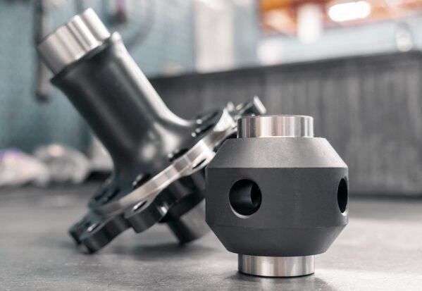
El diseño del carrete del diferencial se trata de un bloqueo total a un bajo costo 100% bloqueo el 100% del tiempo. Hay dos tipos de carretes de diferencial: carretes completos y mini carretes. Cada uno tiene el mismo objetivo, asegurando que ambas ruedas en un eje determinado reciban el par máximo y giren a la misma velocidad todo el tiempo. Crean un eje sólido. Que es un carrete de diferencial. Los carretes completos están diseñados para reemplazar el carrier. Los ejes se instalan dentro del boquete del carrete y la corona se atornilla directamente a una brida de gran diámetro. Esta configuración elimina los engranajes laterales del diferencial y hace que los ejes traseros actúen como si estuvieran soldados, de modo que cada eje gira a la misma velocidad en cualquier circunstancia de conducción. El compromiso de un carrete El compromiso de un carrete Al igual que con cualquier tipo de modificación drástica, en el camino te encontrarás compromisos. Este carrete de diferencial no es diferente. Dado que los ejes están bloqueados, no existen situaciones en las que las llantas deban girar a una velocidad diferente, ejemplo cuando el vehículo hace un giro en una esquina. Cuando esto sucede, escucharás un chillido en las llantas a veces de forma agresiva, mientras se esfuerzan por completar el giro. El hule/goma es la parte débil. Es lo que se desgasta para permitir la maniobra del vehículo. Al hacerlo, las llantas absorben mucho abuso y tienen un desgaste de forma significativa. También se debe recordar que incluso cuando no se llegue al nivel de los ruidos en las llantas, cualquier desequilibrio en la velocidad resultará en un desgaste de las llantas. En pocas palabras, los carretes se comerán las llantas. Otro compromiso es cómo la unión dentro del diferencial también produce una tensión indebida en los propios ejes. A largo plazo, los ejes pueden deformarse debido a la tensión de torsión a la que están sometidos en la carretera. Cambio en la dinámica de conducción Aquí existe un escenario de causa y efecto. En la mayoría de los casos, agregar un carrete compromete el radio de giro del vehículo. Además, un carrete de diferencial puede ser implacable en carreteras mojadas, durante las nevadas, ya que carece de la finura para manejar en condiciones que requieren diferentes velocidades de las ruedas para garantizar la estabilidad y el control del vehículo. En internet y en los foros puedes encontrar un vehículo equipado con carretes de diferencial, pero es un debate largo. Debido a la naturaleza poco manejable, se recomiendan carretes de diferencial como una excelente opción solo para los vehículos dedicados para el off road y carreras. Carretes de diferencial Completos Un carrete completo reemplazará el carrier, los satélites y los engranajes laterales. La unidad consta de una abertura y una brida de anillo. Los ejes se instalan en la abertura la cual están acanalados para aceptar los ejes. Carretes de diferencial Completos La brida de anillo de los carretes se atornilla a la corona, así la corona y el piñón hacen su trabajo, redirigiendo el torque 90 grados desde el eje de transmisión a las ruedas, pero la carcasa ha perdido su capacidad para diferenciar las velocidades de las ruedas entre las ruedas. Los carretes de Yukon y USA Standard Gear están fabricados de acero 8620 de alta calidad y tratados térmicamente para brindar resistencia adicional para que su diferencial esté listo para la acción extrema en nombre de una máxima tracción. Mini carrete de diferencial Un mini carrete es menos costoso que un carrete completo. Dado que se intercambia en lugar de los engranajes satélitales y los engranajes laterales, la instalación es más fácil, rápida y económica que un carrete completo. Aunque los mini carretes de Yukon y USA Standard Gear están fabricados con acero de aleación 8620 tratado térmicamente, no son tan resistentes como los carretes completos porque los mini carretes confían en el carrier original para su resistencia. Costo versus recompensa Vemos nuestros carretes como una opción más segura para aquellos que están considerando soldar sus engranajes para obtener la misma tracción de eje sólido. El gran problema es que si la soldadura está mal hecha puede fallar. Ya sea por soldaduras débiles o demasiado calor que compromete la estructura de grano del acero y hace que los engranajes se vuelvan frágiles en el punto de soldadura y eventualmente se rompan. Cuando los diferenciales soldados se sueltan, pueden quitar otros componentes ... lo que anula cualquier ahorro de costos con la soldadura. A nuestros ojos, estos carretes son solo para vehículos dedicados a las carreras y off road. Si el vehículo es para carretera se recomienda a los clientes que instalen un bloqueador o un diferencial de deslizamiento limitado. El costo versus capacidad Puedes optar por un bloqueador Spartan, un LSD de posición helicoidal o un bloqueador. Si bien cada uno de estos productos representa una mejor calidad, también implican un aumento en los precios de venta. Un carrete de diferencial completo cuesta entre $320 y $375. Un bloqueador Spartan te puede costar entre $400 a $500, proporciona un bloqueo completo y, aunque ocasionalmente puede hacer clic, es mucho más civilizado que un carrete. Los diferenciales de deslizamiento limitado de posición helicoidal empiezan en $600, mejoran sin problemas la tracción en carretera, pero no brindan bloqueo total. El bloqueador Grizzly de Yukon de selección automática empieza en aproximadamente $780 y ofrece un bloqueo del 100% y una capacidad de desbloquearlo automáticamente cuando sea necesario. Por supuesto, el precio depende de la aplicación, pero por muy poca inversión adicional puede obtener un Bloqueador Spartan o un LSD helicoidal. En muchos casos a largo plazo ahorrarás dinero al no tener que comprar llantas nuevas con regularidad. Si utiliza llantas grandes y caras como las 35, 37 o 40 pulgadas, los ahorros podrían ser sustanciales. Estos carretes de diferencial hacen lo que deben hacer y nosotros construimos los nuestros con materiales de calidad y mano de obra de primer nivel. Pero estos productos se centran estrictamente en vehículos específicos especialmente diseñados para no ser conducidos en carreteras normales o que ni siquiera hagan giros de 90 grados. Considere seriamente las expectativas de uso de su vehículo y considere más que el costo inicial. Vea hacia el futuro, cambiar a un dispositivo de tracción más versátil y fácil de manejar puede ser la mejor opción para su billetera y sus nervios.
DIAGNOSING NOISE (PART 2)
If you’ve been left hanging with a “mystery” differential noise that still refuses to make itself clearly understood, then hopefully this month’s info will lend some more insight. Read this article in Español Anyone who has been involved with four-wheel-drive vehicles has probably heard of or experienced positraction (posi) “chatter”. Posi chatter is noise that is very recognizable and happens when there is too much friction in the clutches. Some hard-core offroaders set up their posi this way intentionally. The noise sounds like someone is pounding on the rear end with a huge sledgehammer. It is most prevalent when backing up in a parking lot (where bystanders will stop and stare), and gets worse as the differential heats up. It also tends to show up on freeway off-ramps and when turning while taking off from a stop sign. Broken spider gears can sound similar to posi chatter, only more consistent, regardless of oil temperature. Broken spider gears will make a grinding or banging sound any time the vehicle is making a turn, and, if they are bad enough, even when going straight. Driveline vibrations can be caused by several problems. Worn universal joints or a driveline that is out of balance are often the problem, but driveline angle can cause a balanced driveline with good U-joints to vibrate. If the U-joints are bad, they can cause several different noises from squeaking, to clunking, to grinding, to vibrations. If the driveline is out of balance, it will vibrate with a steady pitch that increases as the vehicle speed increases. If the pinion shaft is out of alignment and not parallel to the transmission yoke, the difference in the angles between the front and back U-joints can cause the driveline to vibrate. If the vibration is due to improper angles, it will create a cyclic sound that increases and decreases in intensity. An out-of-alignment problem can also be identified by the change in the noise when accelerating or decelerating. As the pinion yoke torques up from acceleration or down from deceleration, the rear U-joint angle changes and causes the vibration to change. A worn side-gear bore in the carrier case will usually cause a clicking sound as the vehicle is coasting down from speeds of about 20 miles per hour to a stop. If the bore that supports the side gear becomes too worn to hold the side gear in place the side gear will “roll over” the spider pinion gears and will make a clicking noise. If your differential problem is still not clear and you don’t want to take the time to look inside for more data, you can always drive it until it breaks. The problem will be much clearer, although much more expensive.
Subscribe To Our Newsletter
Sign up & unlock 5% off. Get news on insider deals, product releases, and expert advice.